[0012]The present invention is directed to a system for transferring mechanical torque variably between a plurality of rotating machines in a turbofan engine. The system couples rotating shafts rotating at differing speeds within a turbofan engine for controllably transferring power between them. To transfer power in the system, a fixed
gear ratio is obtained by coupling the relatively high- and low-speed engine shafts to an magnetic gearbox. A torque sensing mechanism can then be employed within the epicyclic
gear train to transfer power from the LP spool to the HP spool, thereby reducing the required
power extraction from HP spool. Alternatively a magnetic device that relies upon the properties of a
planetary gearbox can used in place of an epicyclic gearbox. This arrangement offers the
advantage of removing the need to mechanically couple the engine spools. This controlled power transfer can be particularly advantageous for extracting increased amounts of mechanical power from an engine, or in enhancing dynamic engine performance. As power is transferred between engine spools and auxiliary loads purely by magnetic forces, the opportunity exists to decouple any or all of the loads to suit
operational requirements. The HP spool can be decoupled from the LP spool for engine starting, as an example, or the spools can be decoupled to increase
transient response by removing the coupled
inertia of the other elements. In a preferred embodiment, additional gearing is provided in order to permit a full range of
operability. Another
advantage of the present invention is that variable power transfer between the engine shafts is accomplished without a mechanical linkage between the engine shafts.
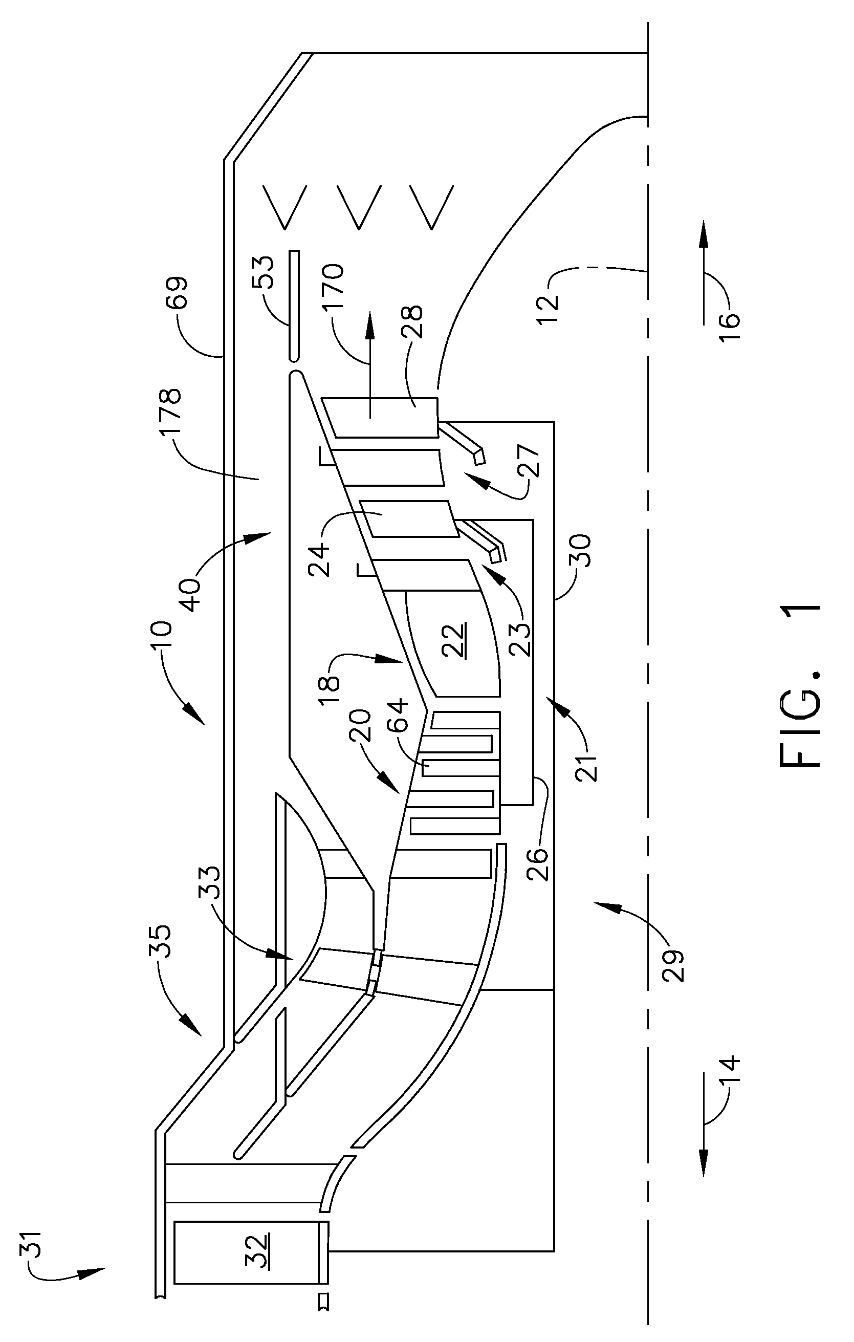
[0013]In another aspect the present invention is directed to a gas
turbine engine. The turbine engine includes a compressor, a
combustor, a
high pressure turbine and a low pressure turbines arranged in serial flow communication and disposed about a longitudinal shaft of the engine within an annular outer casing. The compressor is driven by the
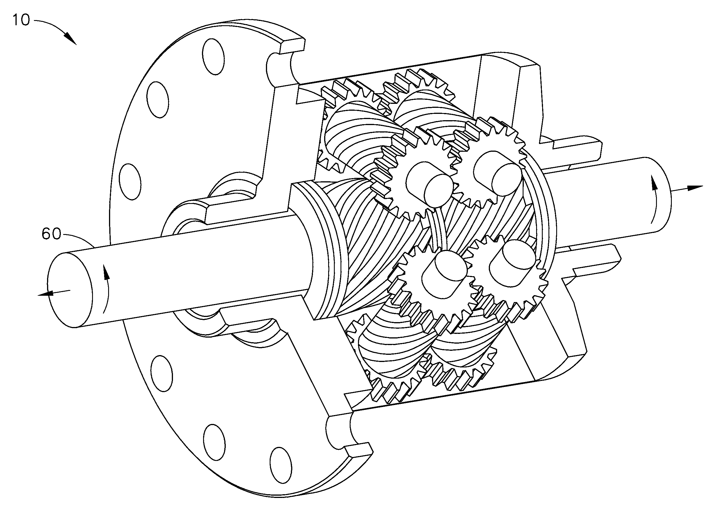
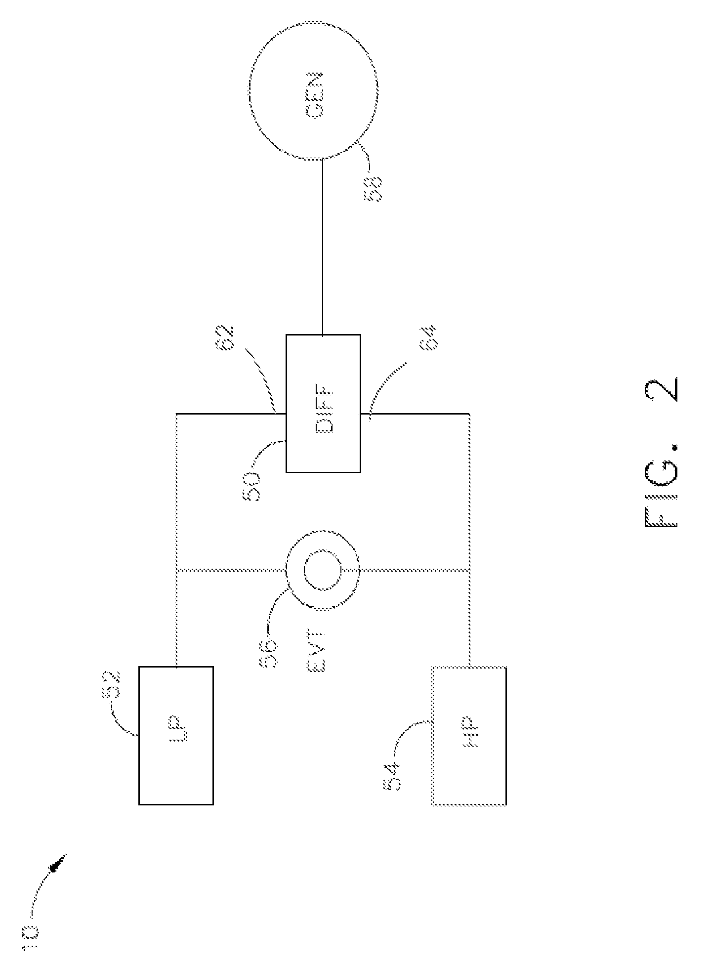
high pressure and low pressure turbines and compressor air during operation. A variable coupler portion is also provided for coupling of a high pressure spool and a low pressure spools to power a generator in a turbofan engine. The variable coupler portion includes a differential gear portion having a first input portion, a second input portion, and an output shaft. An electromagnetic variable transmission has an independently rotatable inner rotor portion and an independently rotatable outer rotor portion. The inner rotor portion is coupled with either the high pressure spool or the low pressure spool, and the outer portion connected to the remaining spool, to transfer torque between the high pressure spool and the low pressure spool. The differential gear portion is connected between the high pressure spool and the low pressure spool in parallel with the electromagnetically variable transmission. The generator is mechanically coupled to the output shaft. The differential gear portion is arranged to equalize the rotational speed of the high pressure spool, the low pressure spool, and the output speed of the output shaft for driving the generator. The EVT is arranged to controllably couple power from the low pressure spool to the high pressure spool.
[0014]The present invention can be located either internal or external to the engine
nacelle or housing. While the variable magnetic gearbox of the present invention is described in association with a turbofan engine, it is considered within the scope of the invention to apply the variable magnetic coupling to any
mechanical equipment requiring variable
torque transmission, e.g.,
hybrid automotive transmissions.
[0015]In some cases of the present invention, it may also be desired to couple additional power on to the HP spool. When additional power is transferred and made available from the LP spool to HP, the
power split can be configured more heavily toward the HP spool. This can result in a lower speed range at the load. Mechanisms for accomplishing this added coupling, and the benefits of it, are within the scope of the present invention and explained in further detail below.
[0016]One disclosed system for coupling additional power to the HP spool uses electromagnetically variable transmission (EVT). The EVT permits controllable coupling of torque from the LP spool to the HP spool, when added power is needed from the HP spool. By providing this function, the ratios of the open differential can be selected to bias the power draw more heavily from the HP. A planetary gear box (PGB) may also be substituted for the open differential, since the PGB performs the same function of splitting torque and speed. In so doing, the speed range of the differential output (or PGB carrier) is reduced. In turn, this permits the
sizing of an electrical generator to be more favorable, as well as the electrical
operating frequency of the connected power system. This enables the use of the EVT where physically smaller systems are required.
[0017]Another method for coupling additional power to the HP spool is through the application of a limited-slip differential. In a conventional automobile application, a limited-slip differential prevents the wheel speeds from diverging by more than a configured amount, by providing extra torque to the slower wheel, and less to the faster wheel. This helps to ensure that the power transmitted to both wheels remains within a desired range. The same principle applies in the present invention where the HP spool and LP spool input speeds to the differential are such that the slip-limiting mechanism of the differential is engaged and biases the
torque transmission more strongly from the HP spool during certain engine operating conditions. One system for providing such a torque biasing is a Torsen™ differential. The Torsen™ differential does rely in part on friction to transmit torque using thrust plates, but it does not require clutches or disks that are typically subject to higher wear rates.

