Eureka AIR delivers breakthrough ideas for toughest innovation challenges, trusted by R&D personnel around the world.

Cyclic Chemical Vapor Deposition of Metal-Silicon Containing Films

a technology of metal-silicon containing films and chemical vapor deposition, which is applied in the direction of crystal growth process, polycrystalline material growth, chemically reactive gas growth process, etc., and can solve problems such as potential hazards

Active Publication Date: 2008-06-19
VERSUM MATERIALS US LLC
View PDF37 Cites 10 Cited by
  • Summary
  • Abstract
  • Description
  • Claims
  • Application Information

AI Technical Summary

Benefits of technology

[0009]an ability to produce high quality ternary metal silicon nitride films;
[0010]an ability to form high quality films while eliminating some of the common precursors that present significant safety and corrosion issues;
[0013]an ability to achieve excellent deposition rates in a cyclic CVD, thus making possible an increase of wafer throughput at production scale;
[0014]an ability to produce metal silicon nitride films using two precursors while eliminating the use of a separate nitrogen source, e.g., ammonia;
[0015]an ability to reduce the metal center in a resulting metal silicon, thus reducing the resisitivity of the resulting film;

Problems solved by technology

Silane is a pyrophic gas, implying a potential hazard.

Method used


Image

  • Cyclic Chemical Vapor Deposition of Metal-Silicon Containing Films
  • Cyclic Chemical Vapor Deposition of Metal-Silicon Containing Films
  • Cyclic Chemical Vapor Deposition of Metal-Silicon Containing Films

Examples


example 1

Deposition of TiSiN Films From TDMAT and DIPAS At 350° C.

[0041]The cyclic chemical vapor deposition was conducted in an ALD reactor similar to what described in the literature (Becker, J. S., S. Suh and R. G. Gordon, Chem. Mater. 15, 2969-2976 (2003)). Di-isopropylaminosilane (DIPAS) was placed in a stainless steel container and heated to 50° C., at which temperature the vapor pressure of DIPAS is about 85 torr. Tetrakis(dimethylamido)titanium (TDMAT) was placed within a separate stainless steel container and heated to 50° C., at which temperature the vapor pressure of TDMAT is about 0.6 torr. Nitrogen was supplied at 15 psig to mass flow meters. Silicon substrates were prepared by breaking six-inch silicon wafers into one-inch squares. Five of the silicon substrates were from 20 ohm-cm wafers and 2 were 1-25 ohm-cm with 1000 Å thermal oxide. The seven wafer substrates were then placed onto a half round substrate holder with dimension of 11 inches long by 1.5 inches across. A carbon...

example 2

Deposition of TiSiN Films From TDMAT and DIPAS At 350° C.

[0044]The cyclic chemical vapor deposition processes with 500 cycle times was also conducted in accordance with the other process steps of Example 1. The deposition rates range from 2 to 3 Å / cycle depending on the positions of wafer pieces.

EXAMPLE 3

Deposition of TiSiN Films From TDMAT and DIPAS At 350° C.

[0045]The cyclic chemical vapor deposition processes with 1500 cycle times was also conducted in accordance with the other process steps of Example 1. The deposition rates range from 2 to 3 Å / cycle depending on the positions of wafer pieces.

example 4

Deposition of TiSiN Films From TDMAT and DIPAS At 325° C.

[0046]Example 1 was repeated with substrate temperature at 325° C. The deposition rates range from 0.4 to 0.7 Å / cycle depending on the positions of wafer pieces


PUM

PropertyMeasurementUnit
temperaturesaaaaaaaaaa
Pressuresaaaaaaaaaa
time periodaaaaaaaaaa

Abstract

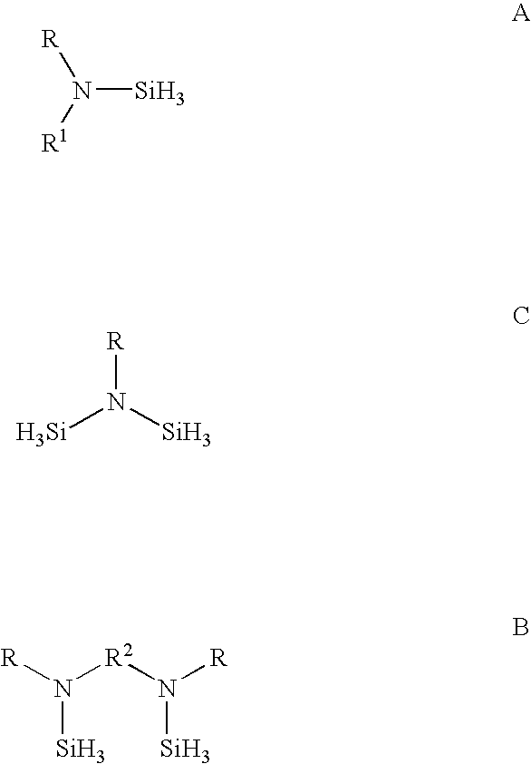
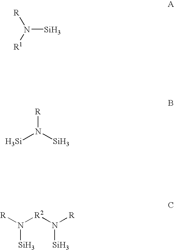
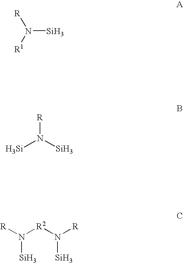
A process to deposit metal silicon nitride on a substrate comprising: sorbing a metal amide on a heated substrate, purging away the unsorbed metal amide, contacting a silicon-containing source having one or more Si—H3 fragments with the heated substrate to react with the sorbed metal amide, wherein the silicon-containing source has one or more H3Si—NR02(R0═SiH3, R, R1 or R2, defined below) groups selected from the group consisting of one or more of:wherein R and R1 in the formulas represent aliphatic groups typically having from 2 to about 10 carbon atoms, e.g., branched alkyl, cycloalkyl with R and R1 in formula A also being combinable into a cyclic group, and R2 representing a single bond, (CH2)n, a ring, or SiH2, and purging away the unreacted silicon-containing source.

Description

CROSS REFERENCE TO RELATED APPLICATIONS[0001]This patent application claims the benefit of US Provisional Patent Application No. 60 / 874,653 filed Dec. 13, 2006.BACKGROUND OF THE INVENTION[0002]Metal silicon nitride films have potential use as diffusion barrier for copper interconnect or as gate electrodes or as heater for phase change memories. Currently, metal amide, silane, and ammonia have been investigated for making metal silicon nitride. Silane is a pyrophic gas, implying a potential hazard.BRIEF SUMMARY OF THE INVENTION[0003]The present invention is a process to deposit metal silicon nitride on a heated substrate comprising:[0004]a. contacting a heated substrate with a metal amide to sorb the metal amide on the heated substrate,[0005]b. purging away any unsorbed metal amide,[0006]c. contacting the heated substrate with a silicon-containing source having one or more Si—H3 fragments to react with the sorbed metal amide, wherein the silicon-containing source has one or more H3Si...

Claims


Application Information

Patent Timeline
Patent Type & Authority Applications(United States)
IPC IPC(8): C23C16/06
CPCC23C16/45553C23C16/34C23C16/06C23C16/56C23C16/0209
Inventor LEI, XINJIANTHRIDANDAM, HAREESHXIAO, MANCHAOBOWEN, HEATHER REGINAGAFFNEY, THOMAS RICHARD
Owner VERSUM MATERIALS US LLC
Why Eureka
Eureka Blog
Learn More