Electrochemical Cell With A Catalytic Electrode And Process For Making The Electrode And The Cell

a catalytic electrode and electrochemical cell technology, applied in the field of catalytic electrodes, can solve the problems of placing restrictions and adding costs to the manufacturing process that can be undesirable, and achieve the effect of convenient, economical and safe manner

Inactive Publication Date: 2008-07-03
EVEREADY BATTERY CO INC
View PDF47 Cites 52 Cited by
  • Summary
  • Abstract
  • Description
  • Claims
  • Application Information

AI Technical Summary

Benefits of technology

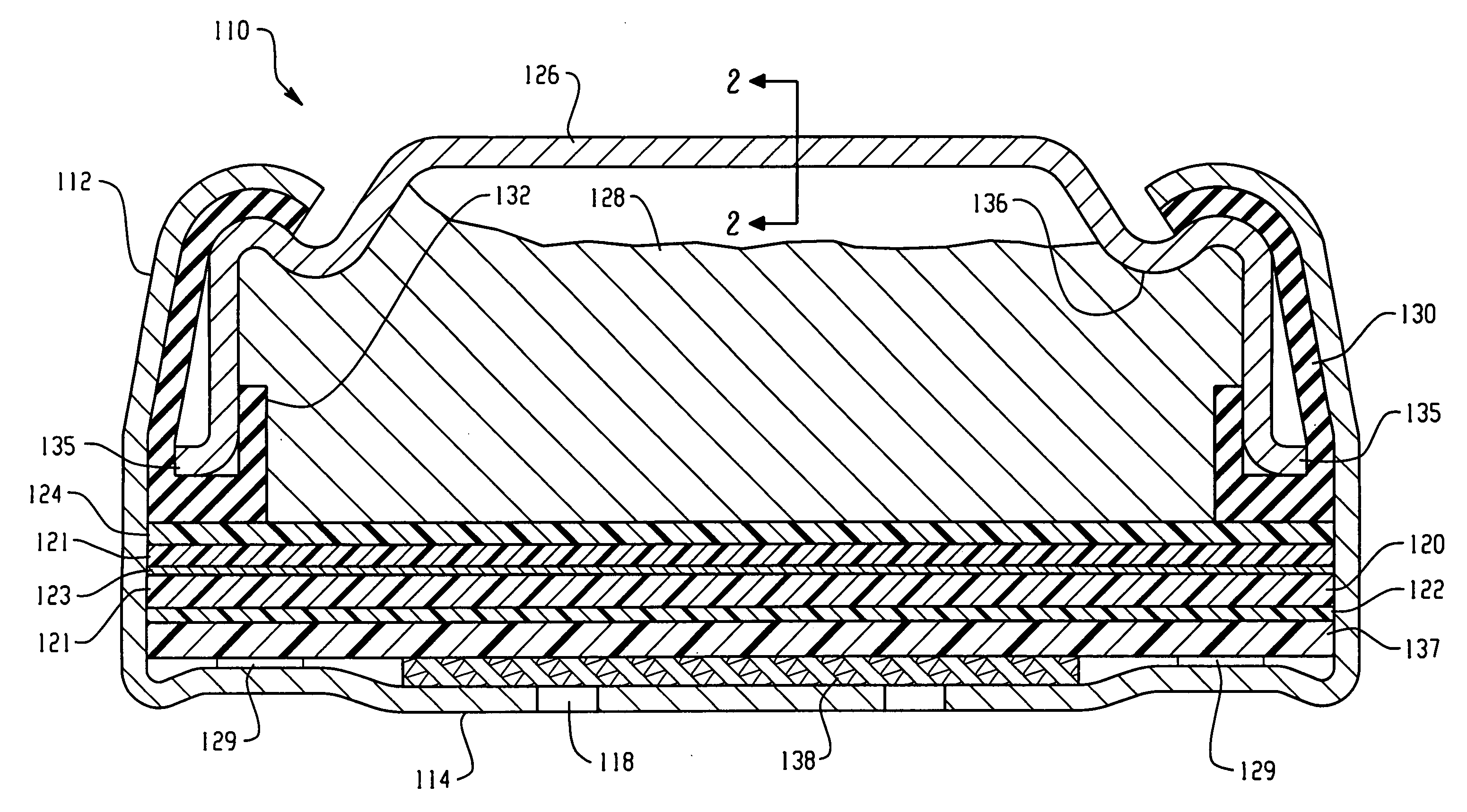
[0008]Some disclosed embodiments provide a process for manufacturing a catalytic electrode and / or an electrochemical cell using the catalytic electrode in an easy, economical and safe manner. Some embodiments eliminate the need for mixing in an inert atmosphere the components of the catalytic material or the resultant catalytic composition used to make the active layer of the electrode. Some embodiments eliminate the use of liquids that are highly volatile, flammable and / or explosive, that may pose potential health risks to workers, or that may pose a risk to the environment.
[0009]Some embodiments provide a catalytic electrode with a nano-catalyst material that has improved electrical properties and that will work well in an electrochemical cell when operated at high power.
[0010]Some embodiments provide an electrochemical cell that has good leakage resistance and improved performance (e.g., greater energy density, improved discharge capacity, and higher power on discharge) than cells made according to the prior art and is also stable during periods of storage and non-use.

Problems solved by technology

This places restrictions on and adds cost to the manufacturing process that can be undesirable, especially for large scale, high speed manufacturing.

Method used


Image

  • Electrochemical Cell With A Catalytic Electrode And Process For Making The Electrode And The Cell
  • Electrochemical Cell With A Catalytic Electrode And Process For Making The Electrode And The Cell
  • Electrochemical Cell With A Catalytic Electrode And Process For Making The Electrode And The Cell

Examples


example 2

[0100]A nano-catalyst air electrode was made with nano-MnOx according to the following steps:[0101]1. 300 g DARCO® G-60 carbon was placed in a 2000 ml glass container, 1000 g distilled water was added, and the container was covered and allowed to sit for one hour.[0102]2. The mixture was mixed for about 30 minutes with an adjustable speed mixer, adjusting the speed to maintain a vortex extending about half way to the bottom of the container.[0103]3. 55 g T30B PTFE was added dropwise while mixing, and mixing was continued for about 20 minutes, adjusting the speed to maintain the desired vortex.[0104]4. The mixture was filtered, while rinsing with about 200 ml distilled water.[0105]5. The remaining solids (the mix) were dried at about 85-90° C. for about 16 hours, then the temperature was increased to 105° C. and drying continued until the temperature of the mix reached 105° C.; then the mix was covered and allowed to cool to room temperature.[0106]6. In an argon gas atmosphere, 10 gr...

example 3

[0113]A sheet of BVA 02530 separator (Hollingsworth & Vose) was glued to the electrode sheets from each of Examples 1 and 2, on the surfaces of the air electrodes opposite the PTFE membranes, using pressure and a PVA / CMC adhesive. Sample electrodes were cut from each of the sheets and assembled into PR44 size alkaline zinc-air button cells.

[0114]Cells with electrodes from each of Examples 1 and 2 were tested for open circuit voltage, followed by AC impedance, with a peak to peak potential amplitude of 10 mV, over a frequency range from 65 KHz to 0.1 Hz. This was followed by a potential dynamic scan in the cathodic direction, beginning at 0.025 V above the open circuit voltage and scanning at 1 mV / sec. to 0.7 V. This initial AC impedance and potential dynamic scan testing served to condition the catalytic electrodes. After 30 minutes open circuit, the AC impedance and potential dynamic scan tests were repeated, and these results were used. From the potential dynamic voltage scan, a v...

example 4

[0116]A nano-catalyst air electrode was made with nano-MnOx according to the following steps:[0117]1. 200 g DARCO® G-60 carbon was placed in a 1500 ml glass container, 900 g distilled water was added, and the container was covered and allowed to sit for about 15 minutes.[0118]2. The mixture was mixed for about 15 minutes with an adjustable speed mixer, adjusting the speed to maintain a vortex extending about half way to the bottom of the container.[0119]3. Mixing was continued while 5.6 g nano-MnOx (QSI-NANO® Manganese) was slowly (over about 30 seconds) added to the vortex and the sides of the container were rinsed with deionized water, followed by about 15 minutes of additional mixing, adjusting the mixer speed to maintain the desired vortex.[0120]4. Mixing was continued while 26 g of T30B PTFE was added dropwise to the vortex, followed by about 20 minutes of additional mixing, adjusting the mixer speed to maintain the desired vortex.[0121]5. The mixture was filtered, while rinsin...


PUM

PropertyMeasurementUnit
BET specific surface areaaaaaaaaaaa
thicknessaaaaaaaaaa
temperatureaaaaaaaaaa

Abstract

A process for making a catalytic electrode containing a transition metal nano-catalyst without using spray or thermal decomposition, and a process for making an electrochemical cell with a catalytic electrode. The nano-catalyst is a particulate material that includes particles that are at least partially oxidized, preferably to include at least oxide shells, before mixing with an activated carbon and binder in a liquid medium to adhere particles of the nano-catalyst to internal and external surfaces of the particles of activated carbon. Oxidation of the nano-catalyst particles allows the mixing of the nano-catalyst, activated carbon and binder in air rather than an inert gas atmosphere and can avoid the use of potentially dangerous liquid media such as highly volatile alcohols.

Description

CROSS-REFERENCE TO RELATED APPLICATIONS[0001]This application claims the benefit of U.S. Provisional Application No. 60 / 877,251, filed Dec. 27, 2006.BACKGROUND[0002]This invention relates to a catalytic electrode, particularly an electrode with a nano-catalytic material, an electrochemical cell containing the catalytic electrode, and processes for making the catalytic electrode and the electrochemical cell.[0003]There is a wide variety of electrochemical cells that have catalytic electrodes. Examples include, but are not limited to, fuel cells, metal-air battery cells, gas (e.g., hydrogen) generating cells, and electrochemical sensor cells. Examples of such cells are found in U.S. Pat. Nos. 5,242,565; 5,308,711; 5,378,562; 5,567,538; 5,707,499; 6,060,196; 6,461,761; 6,602,629; 6,911,278; 7,001,689 and 7,001,865; and in International Patent Publication No. WO 00 / 36677.[0004]An advantage of cells with catalytic electrodes is that they can use one or more active materials that are not ...

Claims


Application Information

Patent Timeline
Patent Type & Authority Applications(United States)
IPC IPC(8): H01M4/62B05D5/12
CPCH01M4/8605H01M4/8668H01M4/8673H01M4/8875H01M4/8896H01M4/90Y10T29/49115H01M8/0206H01M12/06Y02E60/50Y10T29/417Y10T29/49002Y10T29/49108H01M4/9083Y02P70/50H01M4/86H01M4/88B82Y30/00
Inventor DOPP, ROBERT BRIANBENNETT, WAYNE B.GUO, JINGDONG
Owner EVEREADY BATTERY CO INC
Why Eureka
Try Eureka