Hybrid vehicle and hybrid power system

a hybrid power system and hybrid technology, applied in the direction of mechanical equipment, electric propulsion mounting, transportation and packaging, etc., can solve the problems of inability to achieve the required power effect, limited power efficiency of these new power sources, and inability to use a single power source, so as to improve the power transmission efficiency of the automatic manual transmission system, speed change is smooth, and the effect of reducing the abrasion of the gear shifting devi

Inactive Publication Date: 2008-07-03
IND TECH RES INST
View PDF14 Cites 30 Cited by
  • Summary
  • Abstract
  • Description
  • Claims
  • Application Information

AI Technical Summary

Benefits of technology

[0012]In order to solve the above conventional problems, the present invention is directed to a hybrid power system and vehicle, which has a smooth gear-shifting by controlling the rotation speed with a dual-motor. The gear-shifting can be performed when the clutch is not disengaged (definitely, the gear-shifting can also be performed when the clutch is disengaged), so that the speed changes more smoothly, and the abrasion of the gear-shifting device is reduced, thus improving the power transmission efficiency of the automatic manual transmission system.

Problems solved by technology

Among the above power sources, some have a preferred power effect and superior durability, but actually does not conform to the environmental protection requirement, while others conforms to the environmental protection requirement, but cannot achieve the required power effect.
For example, although an electric automobile and a solar energy automobile do not adopt the conventional fuel engine, the power efficiency of these new power sources is limited.
Therefore, it is unfeasible to merely use a single power source.
1. The gear-shifting is completed by controlling the rotation speed of a single motor, such that the speed of the shifting is not quick, and the shifting is not smooth, so that it is difficult to improve the efficiency of the transmission.
2. The disc clutches according to the prior art can be substantially classified into two types, namely a mechanical type and a hydraulic type. The mechanical type uses an actuation lever to manipulate the engage and disengage of the clutch mechanically, which has a complicated mechanism and high cost of parts. The hydraulic type directly actuates the clutch by using an oil hydraulic pump to drive the oil cylinder instead of using the lever to actuate the clutch, which has a high cost of the oil hydraulic system, possibly has the oil leakage problem, and is difficult to be assembled and maintained. Moreover, the actuations of the two types are slow, such that the engage and disengage of the clutch are not smooth, and the transmission efficiency is reduced.

Method used


Image

  • Hybrid vehicle and hybrid power system
  • Hybrid vehicle and hybrid power system
  • Hybrid vehicle and hybrid power system

Examples


first embodiment

The First Embodiment

[Hybrid Vehicle]

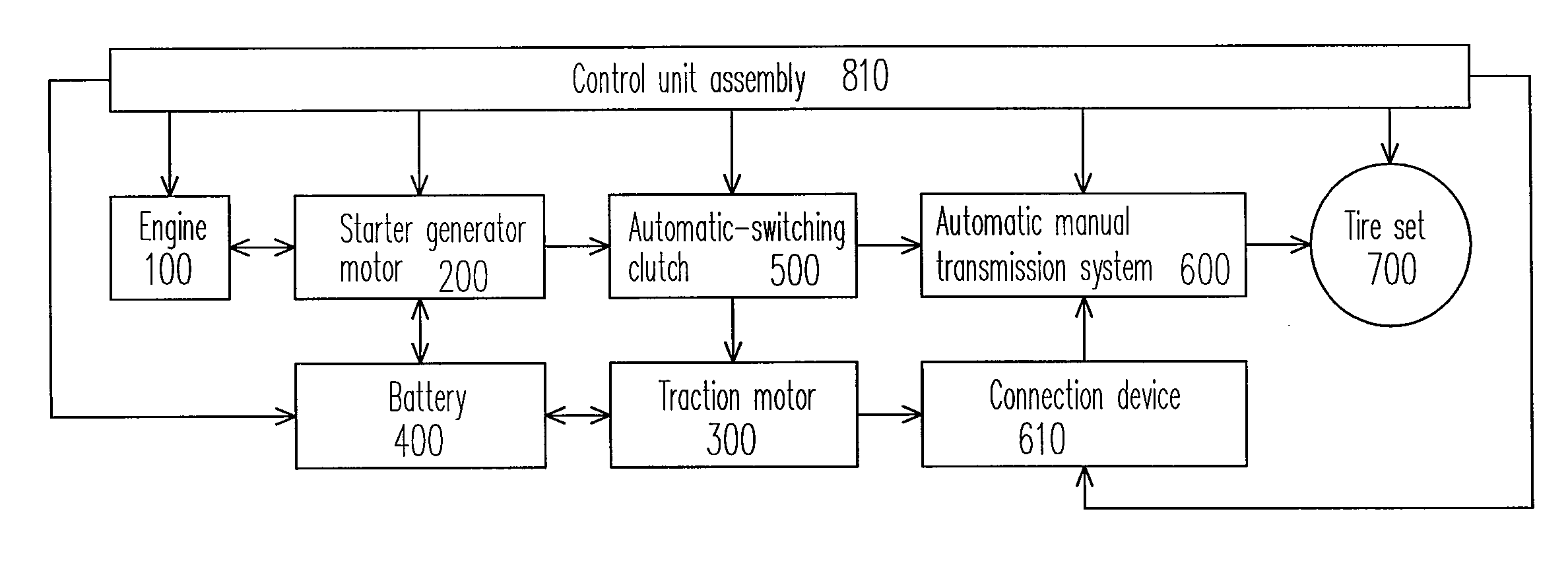
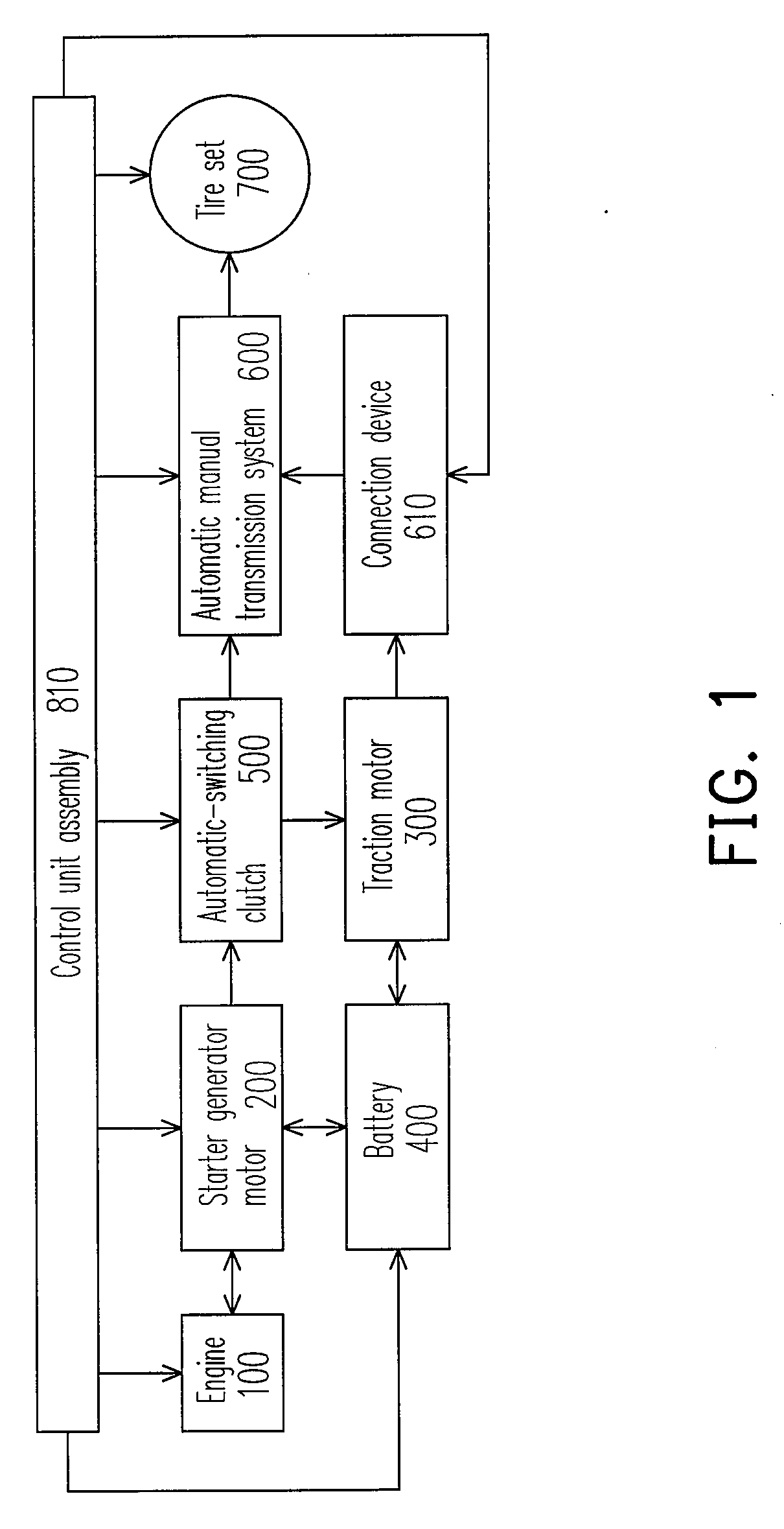
[0042]FIG. 1 is a block diagram of a hybrid vehicle according to a first embodiment of the present invention.

[0043]The hybrid vehicle using at least two energies of the present invention includes an engine 100 serving as a first power, a starter generator motor 200, a traction motor 300 serving as a second power, a battery 400, an automatic-switching clutch 500, an automatic manual transmission system 600, a connection device 610, a tire set 700 and a transmission shaft (not shown), and a control unit assembly (a power-type-controlling unit) 810.

[0044]The starter generator motor 200 is coupled with the engine 100, and synchronously rotates with the engine 100 for starting the engine 100 and serving as an assistant power.

[0045]The automatic manual transmission system 600 is coupled with the traction motor 300 through a connection device 610. Herein, the connection device, for example, includes a gear set, a sprocket and chain set, a belt and pulley...

example 1

[Mechanical Arrangement Example 1]

[0050]Referring to FIGS. 2 and 3, FIG. 2 is a schematic view of a mechanical arrangement of the above components according to Example 1, and FIG. 3 is a partial enlarged view of the dashed area of FIG. 2.

[0051]The starter generator motor 200 and the automatic-switching clutch 500 (for example, an electromagnetic disc clutch) are arranged on the same side of the engine 100. The starter generator motor 200 adopts an inner rotor design. A clutch flywheel 542 is directly locked onto a flange coupling 102f on the left end of the engine crank 102 by using a screw 524b passing through a rotor 202.

[0052]The automatic manual transmission system 600 is connected to a transmission main shaft 650 through a differential 640 and then connected to the tire set 700 (FIG. 1).

example 2

[Mechanical Arrangement Example 2]

[0053]Referring to FIGS. 4 and 5, FIG. 4 is a schematic view of a mechanical arrangement of the above components according to Example 2, and FIG. 5 is a partial enlarged view of the dashed area of FIG. 4.

[0054]The starter generator motor 200 and the automatic-switching clutch 500 (for example, an electromagnetic disc clutch) are arranged on two sides of the engine 100. The starter generator motor 200 adopts an outer rotor design. The rotor 202 is directly locked onto a tapered shaft 102t on the right end of the engine crank 102. A clutch flywheel 542 is directly locked onto a flange coupling 102f on the left end of the engine crank 102.

[0055]The automatic manual transmission system 600 is connected to a transmission main shaft 650 through a differential 640 and then connected to the tire set 700 (FIG. 1).

[0056]In the above two mechanical arrangement examples, the disengagement or engagement of the clutch flywheel 542 and the clutch set 540 involves ...


PUM


Abstract

A hybrid vehicle is provided with an engine, a starter generator motor, a traction motor, an automatic manual transmission system, a battery, an automatic-switching clutch, and a control unit assembly. The starter generator motor is coupled and synchronously rotates with the engine for starting the engine and serving as an assistant power. The automatic manual transmission system is coupled with the traction motor and performs a gear-shifting/speed changing by controlling the rotation speed of the starter generator motor and the traction motor. The automatic-switching clutch is coupled between the starter generator motor and the automatic manual transmission system to make them be engaged/disengaged so as to switch the power type. The hybrid vehicle control device gives a signal to the torque/rotation speed control device to control the automatic-switching clutch to engage/disengage the engine and the traction motor according to the running state of the vehicle.

Description

CROSS-REFERENCE TO RELATED APPLICATION[0001]This application claims the priority benefit of Taiwan application serial no. 95149455, filed Dec. 28, 2006. All disclosure of the Taiwan application is incorporated herein by reference.BACKGROUND OF THE INVENTION[0002]1. Field of the Invention[0003]The present invention relates to a hybrid vehicle and a hybrid power system.[0004]2. Description of Related Art[0005]With the continuous decrease of global crude oil resources and the increase of petroleum price, all the countries actively seek for other alternative energies and the energy conservation methods to alleviate the impact of petroleum crisis.[0006]Currently, the power sources that can be used in the automobile include fuel (diesel fuel, gasoline) engines, solar energy power systems, and electric drive systems, and so on. Among the above power sources, some have a preferred power effect and superior durability, but actually does not conform to the environmental protection requirement...

Claims


Application Information

Patent Timeline
Patent Type & Authority Applications(United States)
IPC IPC(8): B60W10/00
CPCB60K1/02Y10T477/26B60K6/387B60K6/405B60K6/442B60K6/485B60K6/547B60W10/02B60W10/06B60W10/08B60W20/00Y02T10/6226Y02T10/6234Y02T10/6286B60K6/26H02K7/003Y02T10/62B60K2006/268B60K6/36B60W30/19B60W2510/10B60W20/30
Inventor WEI, TSENG-TEHGU, HUAN-LUNGCHEN, YEE-RENWU, E-INLO, SHIH-MINGCHENG, SU-FA
Owner IND TECH RES INST
Why Eureka
Try Eureka