Produced water treatment method and apparatus

a technology of produced water and treatment method, applied in the direction of multi-stage water/sewage treatment, separation process, borehole/well accessories, etc., can solve the problems of imposing surcharges and penalties on the entity responsible for the discharge of fluids, contaminated water in fields that can have significant environmental effects, and large quantities of contaminated water. , to achieve the effect of enhancing filtration efficiency, enhancing particle kinetics and cavitation, and enhancing hydrodynamic cavitation

Inactive Publication Date: 2008-07-03
TERVITA +1
View PDF37 Cites 96 Cited by
  • Summary
  • Abstract
  • Description
  • Claims
  • Application Information

AI Technical Summary

Benefits of technology

[0013]The present invention discloses a method and apparatus for separating particles, dissolved matter and chemical sub-fractions from a produced water fluid stream. In one embodiment, the present invention also discloses a novel separator design which creates or enhances particle kinetics and cavitation physics to increase filtration efficiency and provides for the separation of chemical sub-fractions from fluid streams below one micron in size. In one aspect, the untreated produced water is placed under pressure sufficient enhance standard filtration, create or enhance particle kinetic reactions, or to create or enhance hydrodynamic cavitation during the separation process wherein suspended and dissolved contaminants are separated from the fluid stream within the separator by one or more of said processes during the separation phase. The treated fluid can then transported to a product collection tank and discharged or sent to additional treatment or polish mechanisms for further treatment. The particulate matter retained by the reusable filter media is removed by the instantaneous reverse pressurization of the separator thereby forcing treated waste away from the reusable filter media and into a reject tank. The waste from the reject tank can then further be treated, optionally, by further dewatering and minimization processes. Any resulting sludge can be further processed as necessary. The dried waste can then be transported to a waste collection center for appropriate disposal or landfilling. The treated effluent may be safely used in a variety of ways including being discharged to the environment for beneficial reuse (e.g. potable water use or agricultural use), utilized for secondary oil / gas recovery operations or injected into disposal wells.

Problems solved by technology

The safe and effective removal of contaminants from water and other fluids is a consistent problem faced by many industries.
The presence of suspended and / or dissolved solids in water, wastewater and other fluids is undesirable for several reasons.
If established discharge-contamination levels are exceeded, governmental authorities and agencies may impose surcharges and penalties on the entity responsible for the discharge of fluids which does not meet or exceed the appropriate standard of quality.
Both terrestrial and offshore oil and gas fields produce large quantities of contaminated water that can have significant environmental effects if they are not handled, remediated and discharged properly.
The treatment of produced water is a major component of the cost of producing oil and gas.
Other contaminants may include slurries having dispersed oil droplets, dissolved organic compounds including dissolved oil, drilling fluids, polymers, well treatment and workover chemicals, and other organic and inorganic compounds that can lead to toxicity.
Because of the contaminants in produced water, it requires no large amount of thought to surmise that the direct release or reinjection of untreated produced water into the ocean, upon land, or into the subsurface formation would have damaging effects on the environment and pose health risks to animals and humans in both the short and long term.
If oil and gas producers discharge produced waters that contain concentrations of specified contaminants which exceed the specified maximum discharge concentrations, severe fines and potential criminal penalties can result.
There are several problems with this prior art solution.
First, once the disposable filters have been used they are typically considered hazardous waste and they must be sent to special disposal facilities for disposal after use further depleting the increasingly diminishing landfill space available.
Second, the disposable filters are themselves relatively costly and therefore do not provide an economical treatment solution.
Third, the constant changing of used disposable filters with clean or new disposable filters is labor intensive.
Fourth, the disposable filters have a relatively short lifespan as they (1) are constructed of paper-based material which is easily degraded by contaminants, (2) are unable to continually support the sheer mass of the contaminants that are loaded onto the filters during filtration operations, and (3) cannot withstand typical backwash cleaning pressures Consequently, a need exists for a way to minimize or eliminate the need for disposable filters in the removal of suspended solids from waste streams such as produced water.
Another problem encountered in removing contaminants from fluids is the expense and difficulty in designing a system that can remove contaminants that vary widely in chemical and physical make-up.
Such a wide range of contaminants presents several challenges in treating produced waters.
For example, slurries and biological contaminants can plug filtration equipment, and separation of metals from contaminated water typically requires expensive chemical precipitation processes.
Because such treatment facilities are complex, they are typically not mobile, therefore requiring industrial waste water be stored on-site and then shipped to a treatment facility.

Method used


Image

  • Produced water treatment method and apparatus
  • Produced water treatment method and apparatus
  • Produced water treatment method and apparatus

Examples


Embodiment Construction

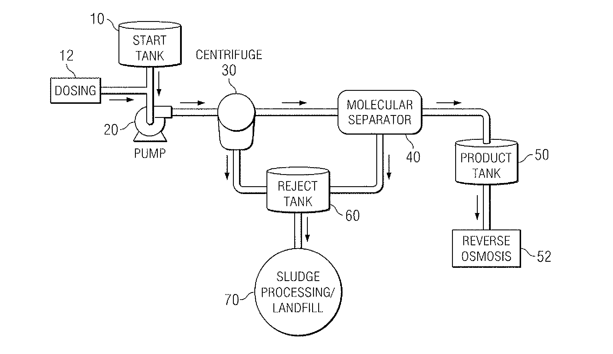
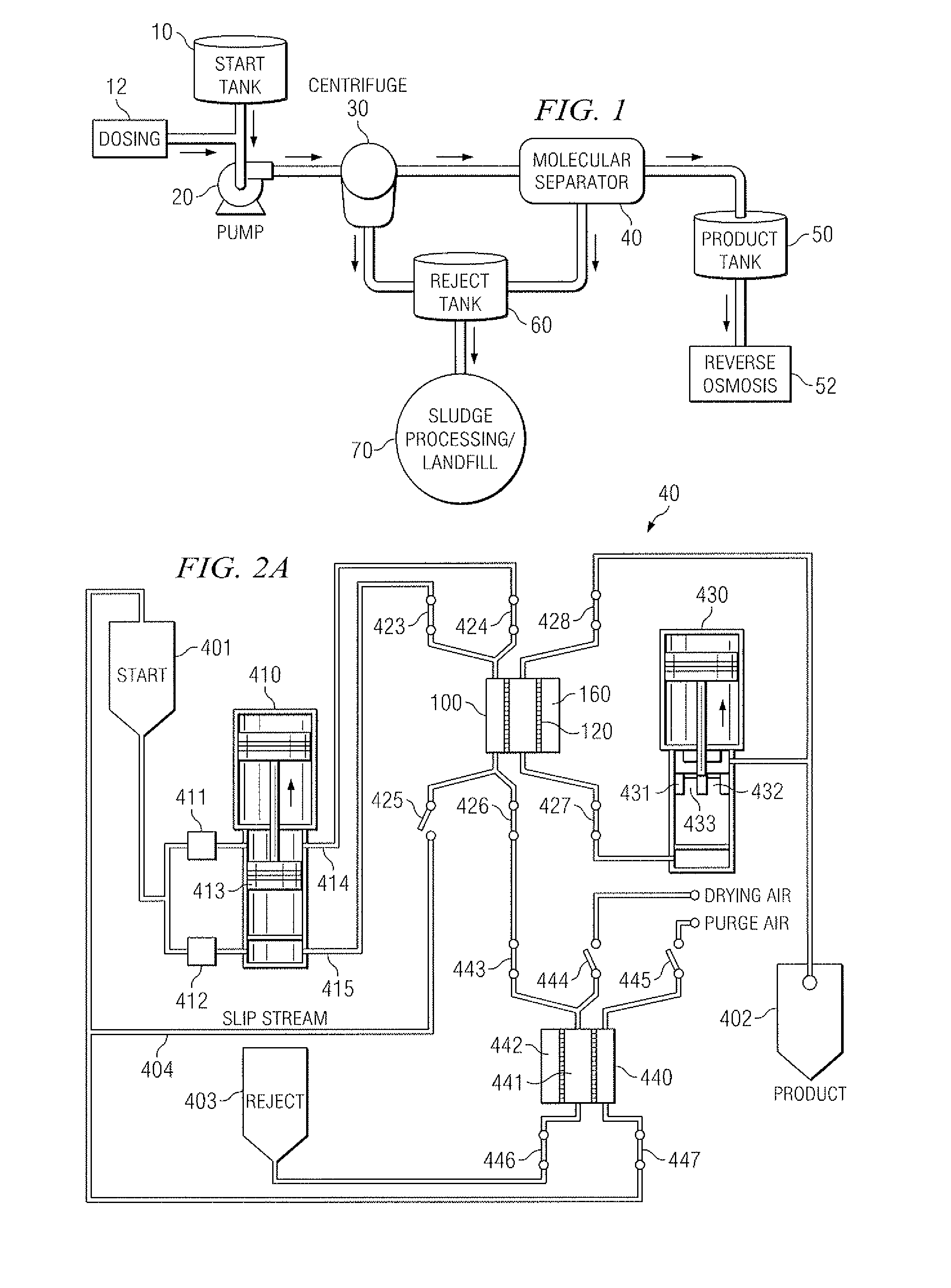
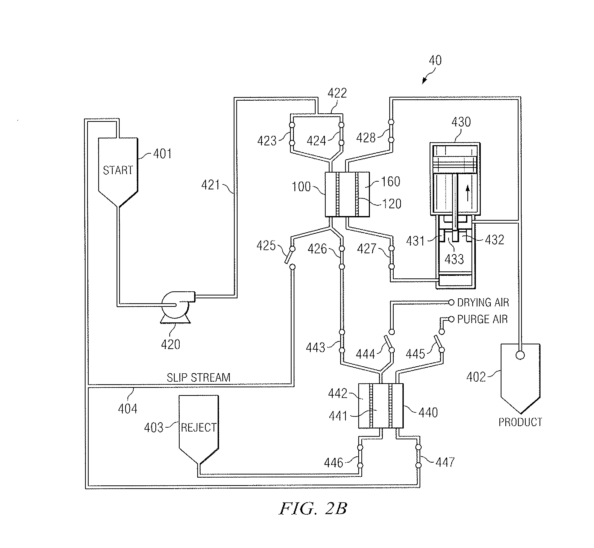
[0033]The present invention is directed towards an improved water treatment system for removing contaminants from water. In one embodiment, the use of hydrodynamic cavitation forces and physics in conjunction with traditional separation media to treat contaminated water is both novel and a significant improvement over existing traditional filtration systems. “Untreated water” is used throughout the detailed description and refers to any water containing one or more contaminants, including, but not limited to “produced water,”“refinery water,”“mining water,” and “pulp / paper wastewater.” As used herein “produced water” is used interchangeably with “untreated water.”

[0034]As used herein, “contaminant” refers to any physical, chemical, biological, or radiological substance or matter that has an adverse effect on air, water, or soil and as a consequence of that impact there is a regulation regarding the discharge of that contaminant into the environment.

[0035]As used herein, “produced wa...


PUM

PropertyMeasurementUnit
particle sizesaaaaaaaaaa
sizeaaaaaaaaaa
pressureaaaaaaaaaa

Abstract

The present invention discloses a method and apparatus for separating particles and dissolved matter from a produced water fluid stream. Specifically, the present invention includes a first pressure source which transports untreated produced water or contaminated aqueous fluid into a separator annulus with a filter element disposed therein. The untreated fluid is placed under appropriate pressure sufficient to produce turbulent flow, increased particle kinetics and/or cavitation allowing the desired fluid to penetrate and pass into and through the filter media. The treated fluid is then transported to a collection tank. The contaminant matter retained by the filter media may be removed by the nearly instantaneous reverse pressurization of the separator annulus by a second pressure source thereby removing the contaminant particles away from contact with the filter media, and which may then be transported to a waste collection tank or a separator for further treatment.

Description

PRIORITY CLAIM[0001]This application is a continuation-in-part and claims the benefit of and priority to co-pending U.S. patent application Ser. No. 11 / 042,235, attorney docket no. CJOHN.00002CIP which was filed on Jan. 25, 2005, which claims the benefit of and priority to U.S. Pat. No. 7,291,267, attorney docket no. CJOHN.00002 filed on Apr. 8, 2004, which claims the benefit of and priority to U.S. Provisional Application No. 60 / 540,492, filed Jan. 30, 2004, the disclosures of which are incorporated herein by reference.BACKGROUND OF THE INVENTION[0002]1. Technical Field[0003]The present invention relates to a system for improving the quality of waters and fluids produced from petroleum and gas well drilling and recovery operations, mining operations, and during other industrial activities, and specifically to a method that does not involve the use of traditional filtration or separation methods. The present system separates contaminants from the water and field produced fluids util...

Claims


Application Information

Patent Timeline
Patent Type & Authority Applications(United States)
IPC IPC(8): B01D65/02
CPCB01D17/0202B01D61/00F04B9/113B01D61/14B01D61/142B01D61/147B01D61/18B01D61/20B01D63/06B01D65/00B01D65/02B01D65/08B01D2321/04B01D2321/2033B01D2321/2066B01D2321/2083C02F1/32C02F1/36C02F1/38C02F1/441C02F1/444C02F1/48C02F9/00C02F2101/32E21B43/34B01D17/085B01D61/146E21B43/35
Inventor JOHNSON, RAYMOND FORD
Owner TERVITA
Why Eureka
Try Eureka