Focused Ion Beam Apparatus

a technology of focusing ion beams and focusing beams, applied in the direction of beam deviation/focusing by electric/magnetic means, instruments, mass spectrometers, etc., can solve the problems of reducing the transmittance of light by ga, affecting the quality of irradiated silicon wafers, etc., to achieve the effect of reducing the transmittance in the correction of the photo mask

Inactive Publication Date: 2008-07-03
SII NANOTECHNOLOGY INC
View PDF13 Cites 7 Cited by
  • Summary
  • Abstract
  • Description
  • Claims
  • Application Information

AI Technical Summary

Benefits of technology

[0032]According to the invention, the beam diameter can be narrowed to the desired value although the plasma type gas ion source is used as the ion source. Thereby, a broad application to a degree the same as that of the case of using the Ga liquid metal ion source as the ion source can be dealt with.
[0033]Further, since the plasma type gas ion source is used, the problem of Ga contamination in a silicon wafer or the problem of the reduction in the transmittance in correcting a photo mask is not posed.

Problems solved by technology

However, when Ga liquid metal is used, the following problem is posed.
Therefore, when a focused ion beam constituting an ion source by Ga liquid metal is irradiated to a silicon wafer even by once, it is difficult to return the irradiated silicon wafer again to a production line in view of maintaining quality.
Further, when the photo mask is corrected, there poses a problem that transmittance of light is reduced by Ga struck to a correcting portion.
The problem becomes a further considerable problem in recent years since short wave formation of an exposure light source is promoted.
Meanwhile, according to the focused ion beam apparatus utilizing the gas ion source as described in Patent Reference 1 or Patent Reference 2, there poses a problem that in comparison with a case of using the ion source of the Ga liquid metal, a beam diameter cannot be narrowed and extremely fine observation or working cannot be carried out.
Therefore, according to the focused ion beam apparatus of the background art, even when only the ion source is replaced by the ICP ion source, the beam diameter D can be narrowed at least to about 100 nm to pose a problem that an application range is much narrowed.
Further, high resolution observation or nanometer working which is carried out under a condition of the beam diameter D of about 4 nm and the beam current equal to or lower than 0.1 pA cannot be carried out.

Method used


Image

  • Focused Ion Beam Apparatus
  • Focused Ion Beam Apparatus
  • Focused Ion Beam Apparatus

Examples


first embodiment

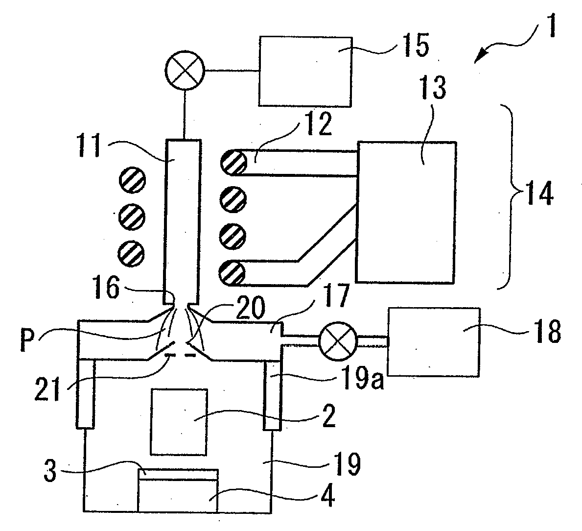
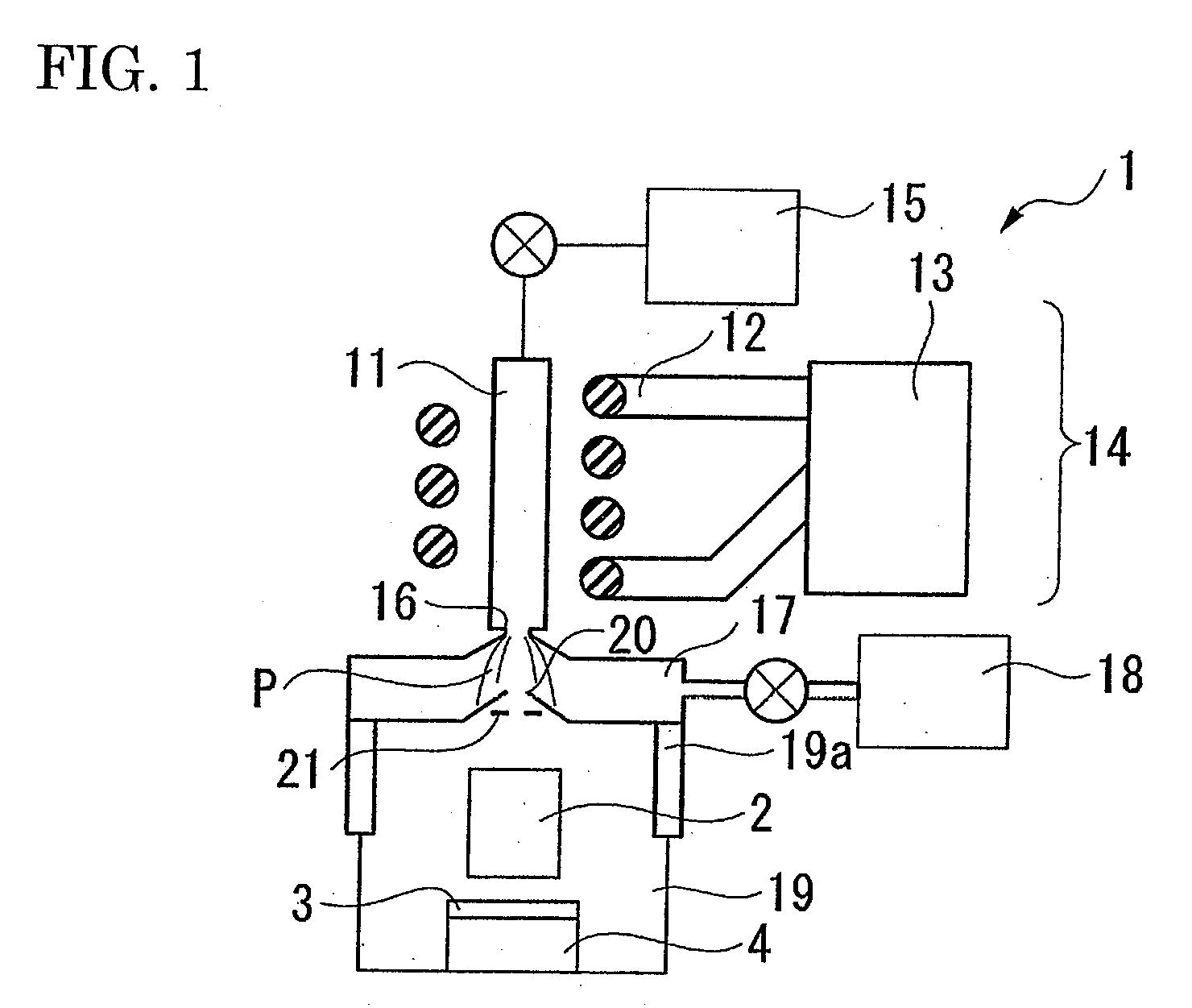
[0045]FIG. 1 through FIG. 4 show a first embodiment of a focused ion beam apparatus, FIG. 1 is a view showing an outline constitution of a total of the apparatus, and FIG. 2 is a view showing a structure at and after a sampling interface.

[0046]In FIG. 1, notation 1 designates a plasma type gas ion source. A downstream side (lower side in FIG. 1) of the plasma type gas ion source 1 is provided with an ion optical system 2 for focusing an ion beam emitted from the plasma type gas ion source 1. On a lower side of the ion optical system 2, a sample base 3 for mounting a sample N constituting an object of working or an object of observation is supported movably by an XYZ stage 4 which is operated in three axes directions orthogonal to each other respectively independently from each other.

[0047]The plasma type gas ion source 1 includes an inductively coupled plasma generator 14 having a plasma torch 11, a work coil 12 arranged to surround the plasma torch 11, and a high frequency power so...

second embodiment

[0069]FIG. 5 shows a structure of a portion (at and after sampling interface) of a second embodiment of a focused ion beam apparatus according to the invention. Further, in order to simplify the explanation, when a constitution element the same as other constituent element used in the first embodiment is used, the constituent element is attached with the same notation and an explanation thereof will be omitted.

[0070]A point of a difference of the second embodiment from the first embodiment resides in that a condenser lens 31 as an auxiliary electrostatic lens is provided between the two lenses 22, 29 other than the condenser lens 22 and the object lens 29 constituting the basic electrostatic lenses.

[0071]Further, also in the second embodiment, a plasma gas type ion source is naturally provided as an ion source.

[0072]By providing the condenser lens 31 constituting the auxiliary electrostatic lens in this way, a range of controlling the ion optical system magnification M can be widene...

modified example

[0076]FIG. 7 shows a modified example of the second embodiment of a focused ion beam apparatus according to the invention.

[0077]According to the example, a situation when the beam diameter is narrowed the most in a small current region is assumed.

[0078]That is, here, when the potential V1 in passing the extraction electrode 21 is set to 100V, the potential V2 in passing the condenser lens 22 is set to 100V, the potential V3 in passing the intermediate region from the condenser lens 22 until reaching the condenser lens 31 on a lower side thereof is set to 30000V, the potential V4 in passing the condenser lens 31 is set to 13000V, the potential V5 in passing the intermediate electrodes of the condenser lens, the beam blanker, the beam alignment and the like is set to 30000V, the potential V6 in passing the object lens 29 is set to 65000V, and the potential V7 of being incident on the sample is set to 30000V, as shown by notation Z in FIG. 7, there are crossovers at two portions and th...


PUM


Abstract

A focused ion beam apparatus including a plasma type gas ion source for generating an ion beam, and an ion optical system for gathering the ion beam generated from the plasma type gas ion source onto a sample. The ion optical system is constructed by a constitution having 2 pieces of basic electrostatic lenses and an ion optical system magnification of the 2 pieces of basic electrostatic lenses is set to be equal to or smaller than 1/300.

Description

[0001]This application claims priority under 35 U.S.C. §119 to Japanese Patent Application No. JP2006-354789 filed Dec. 28, 2006, the entire content of which is hereby incorporated by reference.BACKGROUND OF THE INVENTION[0002]The present invention relates to a focused ion beam apparatus, particularly to a focused ion beam apparatus using a plasma type gas ion source as an ion source.[0003]In a background art, in carrying out extremely fine observation or working for a sample of a photo mask or the like, a focused ion beam apparatus is used. Further, the focused ion beam apparatus is used by switching a beam current in order to deal with a broad application.[0004]For example, when high resolution observation or nanometer working is carried out, the observation or working is carried out by using a beam current equal to or lower than 0.1 pA, further, when high accuracy working of finishing a TEM sample or correcting a photo mask or the like is carried out, the working is carried out b...

Claims


Application Information

Patent Timeline
Patent Type & Authority Applications(United States)
IPC IPC(8): H01J3/14
CPCH01J37/08H01J37/3007H01J2237/31749H01J2237/0817H01J2237/31742H01J37/3056
Inventor SUGIYAMA, YASUHIKO
Owner SII NANOTECHNOLOGY INC
Why Eureka
Try Eureka