Surface mount lateral light emitting apparatus and fabrication method thereof

a technology of surface mount and light emitting device, which is applied in the direction of coatings, solid-state devices, semiconductor devices, etc., can solve the problems of thinning the width of the periphery portion of the concave portion, the die cannot be released from the resin, and the difficulty of molding the resin molding body by injection molding using thermoplastic resin, etc., to achieve good mass-productivity, good resin flow, and the effect of reducing size and weigh

Active Publication Date: 2008-07-03
NICHIA CORP
View PDF43 Cites 45 Cited by
  • Summary
  • Abstract
  • Description
  • Claims
  • Application Information

AI Technical Summary

Benefits of technology

[0032]In the fabrication method of the side-view type light emitting apparatus, the thermosetting resin is injected in a space formed by the upper die and lower die by the transfer molding process from the gate disposed on the side face of the first resin molding body adjacent to the side face of the concave portion of the first resin molding body when the upper die is engaged with the lower die. Therefore, a stress is not applied to the thin periphery portion of the concave portion of the first resin molding body when the die is released from the resin, as well as a good resin flow is achieved. Accordingly, the resin molding body which has a thinner periphery portion of the concave portion for the side-view type light emitting apparatus can be provided.
[0033]With the fabrication method described above, the side-view type light emitting apparatus which is excellent in mass-productivity, molding, heat resistance, and light resistance can be fabricated.
[0034]The side-view type light emitting apparatus according to the present invention can be reduced in size and weight by thinning a width of the periphery portion of the concave portion in the resin molding body. Therefore, a less expensive side-view type light emitting appara

Problems solved by technology

In the side-view type light emitting apparatus, when a width of a periphery portion of the concave portion is made thinner, a molding of the resin molding body by the injection molding using the thermoplastic resin has been difficult due to a low fluidity of the thermoplastic resin.
In addition, when a temperature of the molding is increased for improving the fluidity of the thermoplastic resin, a trouble that a die can not be released from the resin has happened.
Therefore, there has been a limitation for thinning a width of the periphery portion of the concave portion.
Specifically, if the width of the periphery portion of the concave portion is too thinned, a light from a light emitting device entirely passes through the periphery portion, thereby

Method used


Image

  • Surface mount lateral light emitting apparatus and fabrication method thereof
  • Surface mount lateral light emitting apparatus and fabrication method thereof
  • Surface mount lateral light emitting apparatus and fabrication method thereof

Examples


Embodiment Construction

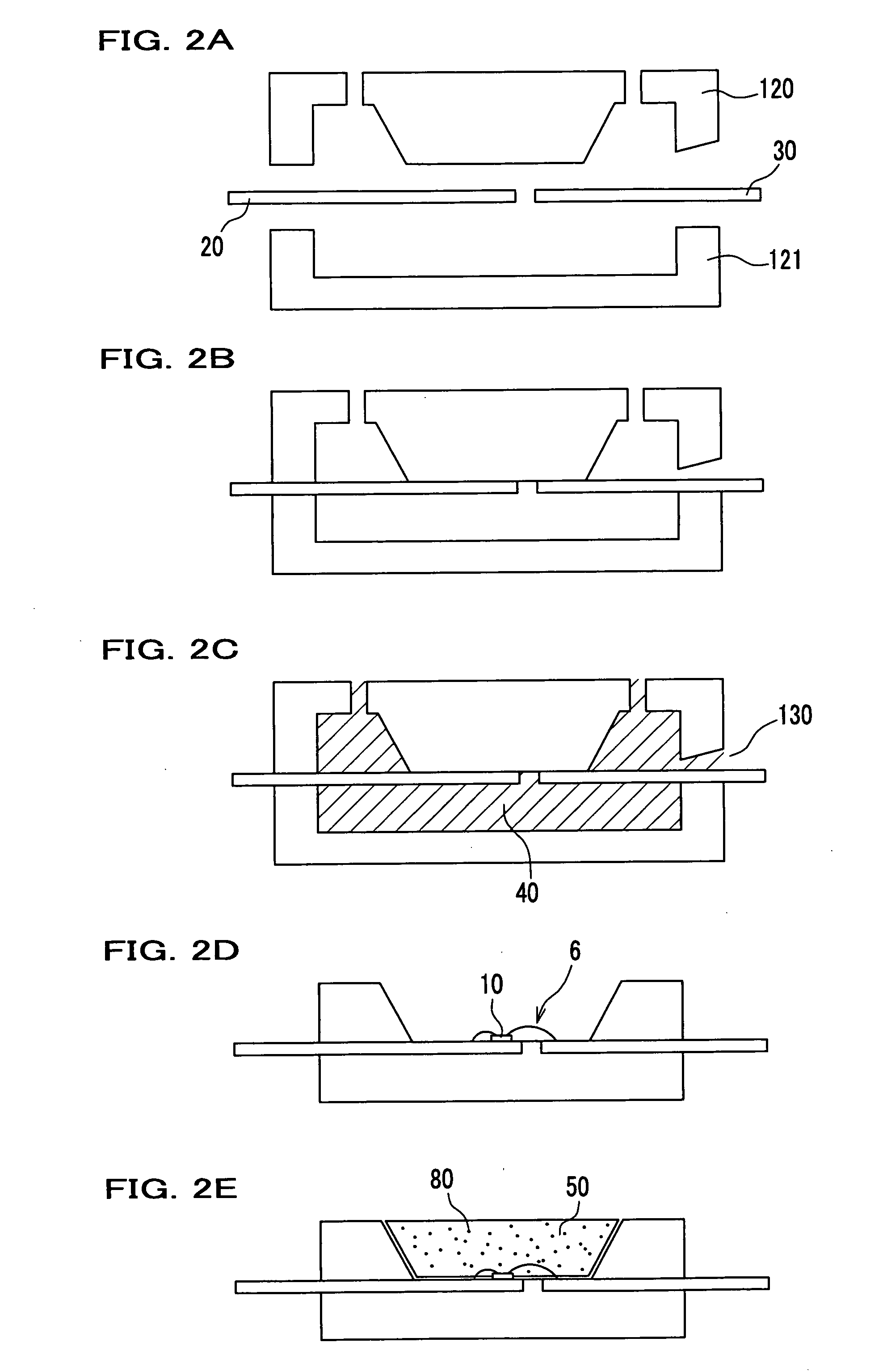
[0041]Hereinafter, an embodiment of a side-view type light emitting apparatus according to the present invention and a fabrication method of the apparatus will be explained by referring to drawings. However, the present invention is not limited to the embodiment.

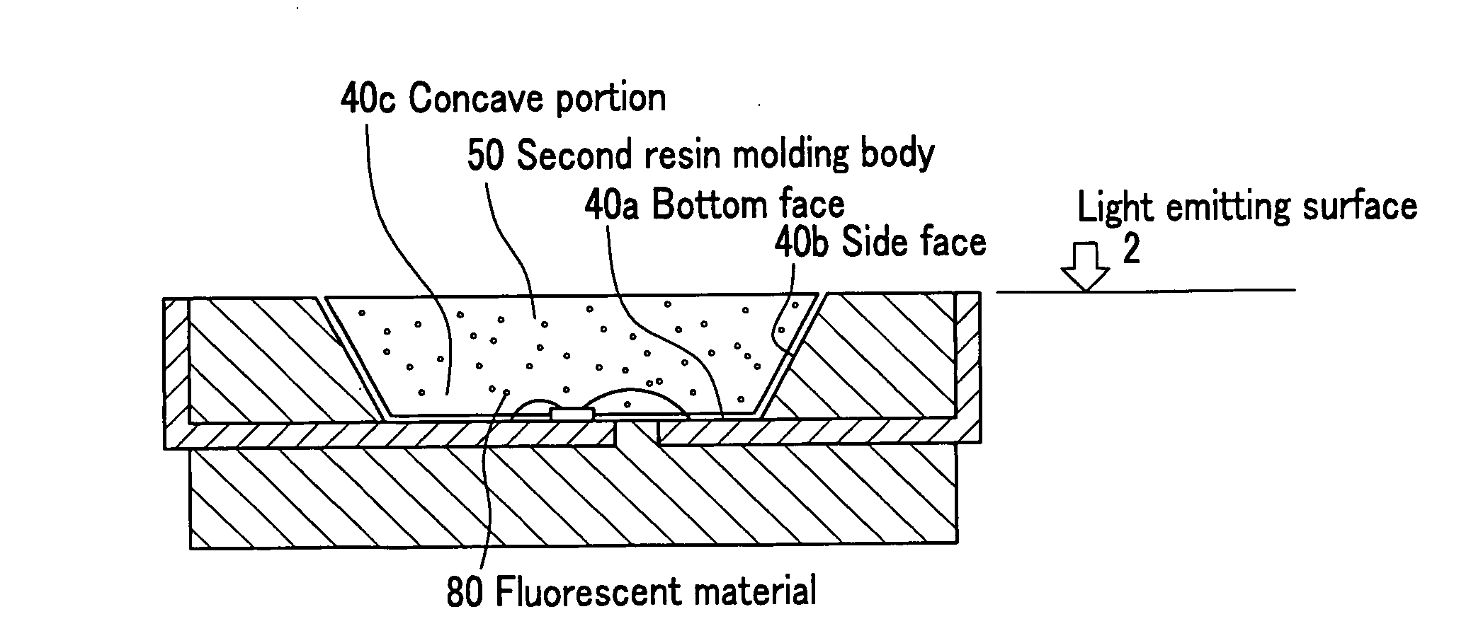
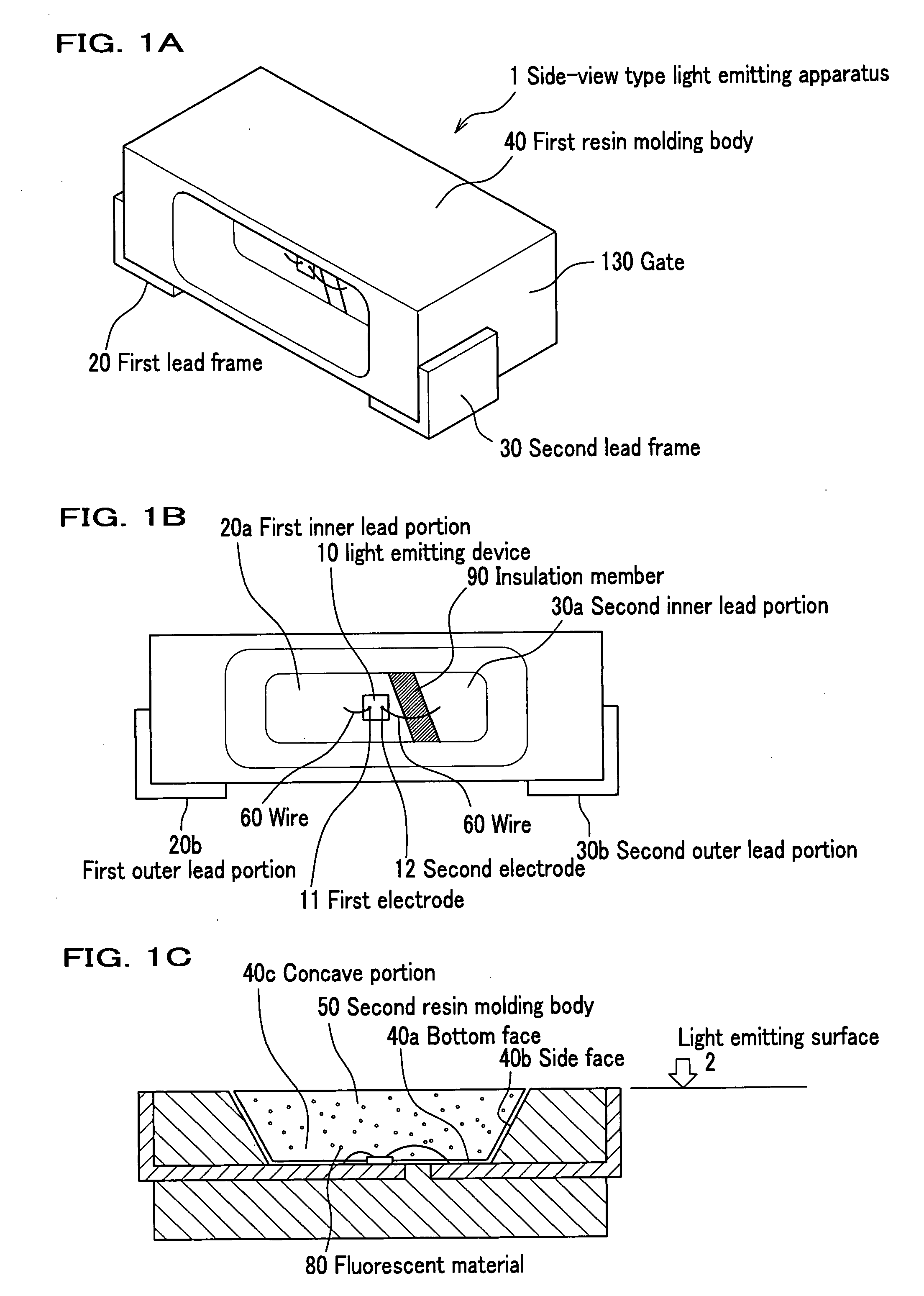
[0042]A perspective view of the whole side-view type light emitting apparatus is shown in FIG. 1A. A front view of the side-view type light emitting apparatus as seen from an opening side of the apparatus is shown in FIG. 1B. A cross sectional view of the side-view type light emitting apparatus as seen from above of the apparatus shown in FIG. 1B is shown in FIG. 1C.

[0043]It is noted that in FIG. 1A and FIG. 1B, for example, a second resin molding body, which will be described later for explanations, will be omitted.

[0044]The side-view type light emitting apparatus according to the embodiment includes a light emitting device 10, a first resin molding body 40 for mounting the light emitting device 10, and a second resin moldi...


PUM

PropertyMeasurementUnit
Lengthaaaaaaaaaa

Abstract

A surface mount lateral light emitting apparatus, which includes a light emitting device; a first lead frame connected to the light emitting device; a second lead frame connected to the light emitting device; a first resin molding body in which a concave portion for mounting the light emitting device is formed and the first lead frame and the second lead frame are fixed; and a second resin molding body which covers the light emitting device to form a light emitting surface in the concave portion of the first resin molding body, wherein the first resin molding body contains a filler or a light diffusion agent; wherein in a periphery of the concave portion, a width of at least one side of the first resin molding body is not more than 0.2 mm; and wherein the first resin molding body and the second resin molding body are formed with a thermosetting resin.

Description

CROSS REFERENCE TO RELATED APPLICATIONS[0001]This application claims the foreign priority benefit under Title 35, United States Code, §119(a)-(d) of Japanese Patent Application No. 2006-355092, filed on Dec. 28, 2006, the contents of which are hereby incorporated by reference.BACKGROUND OF THE INVENTION[0002]1. Field of the Invention[0003]The present invention relates to a surface mount lateral light emitting apparatus (side-view type light emitting apparatus) which is used for, for example, a lighting apparatus, a display, a backlight of a cellular phone, a video auxiliary light source, and other general consumer light sources, and a fabrication method of the surface mount lateral light emitting apparatus.[0004]2. Description of Related Art[0005]A surface mount lateral light emitting apparatus which usually uses, for example, a light emitting diode (LED) is small and excellent in power efficiency, and emits a brilliant color. In addition, since the light emitting device is a semico...

Claims


Application Information

Patent Timeline
IPC IPC(8): H01L33/00H01L33/56H01L33/60H01L33/62
CPCB29C45/0013H01L33/486B29C45/14655B29C45/1671H01L33/52H01L33/54H01L2224/48091H01L2924/01012H01L2924/0102H01L2924/01025H01L2924/01057H01L2924/01063H01L2924/01078H01L2924/01079H01L2924/3025B29C45/14467H01L33/62H01L2924/01066H01L2224/48247H01L2924/00014
Inventor HAYASHI, MASAKI
Owner NICHIA CORP
Why Eureka
Try Eureka