Element Substrate and Light Emitting Device
a technology of light emitting device and element substrate, which is applied in the direction of static indicating device, lighting and heating apparatus, instruments, etc., can solve the problems of variable characteristics and other problems, and achieve the effect of increasing the storage capacity of capacitors, reducing the cause of variation, and enhancing image quality
- Summary
- Abstract
- Description
- Claims
- Application Information
AI Technical Summary
Benefits of technology
Problems solved by technology
Method used
Image
Examples
embodiment mode 1
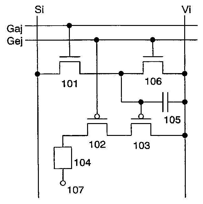
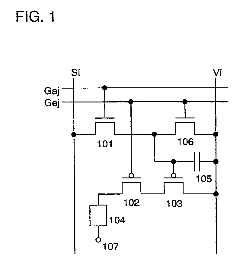
[0040]FIG. 1 shows an embodiment mode of a pixel of the light emitting device of the invention. The pixel shown in FIG. 1 comprises a light emitting element 104, a transistor (switching transistor) 101 used as a switching element for controlling a video signal input to the pixel, a driving transistor 102 for controlling a current value flowing in the light emitting element 104, a current controlling transistor 103 for controlling a current supply (or controlling a light emission or non-emission) to the light emitting element 104, and a transistor (erasing transistor) 106 for turning OFF the current controlling transistor 103 forcibly. In addition, it is also possible to dispose a capacitor 105 for storing a potential of a video signal as shown in this embodiment mode.
[0041]The driving transistor 102 and the current controlling transistor 103 have the same polarity, while the erasing transistor 106 and the driving transistor 102 have the opposite polarity to each other. In addition, ...
embodiment mode 2
[0070]Described in this embodiment mode is another pixel configuration of the light emitting device of the invention which is different from that shown in FIG. 1.
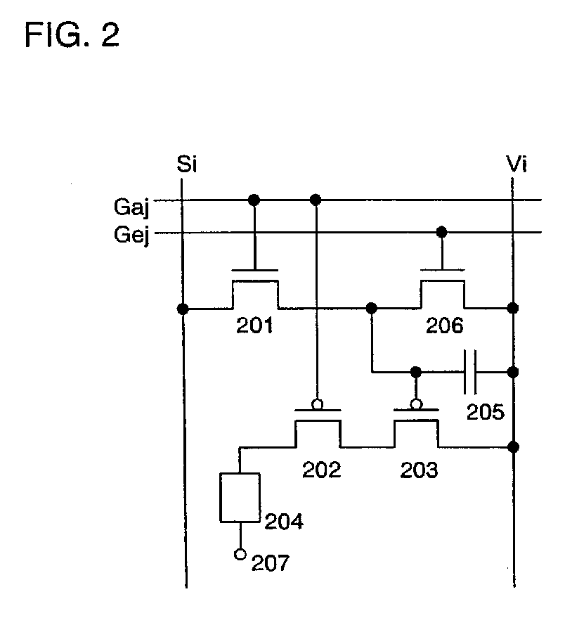
[0071]The pixel shown in FIG. 2 comprises a light emitting element 204, a switching transistor 201, a driving transistor 202, a current controlling transistor 203, and an erasing transistor 206. It is also possible to dispose a capacitor 205 in addition to these elements.
[0072]The driving transistor 202 and the current controlling transistor 203 have the same polarity, while the switching transistor 201 and the driving transistor 202 have the opposite polarity to each other. According to the invention, the driving transistor 202 operates in a saturation region while the current controlling transistor 203 operates in a linear region.
[0073]The channel length (L) of the driving transistor 202 may be longer than its channel width (W), and L of the current controlling transistor 203 may be equal to or shorter than its W. Desirab...
embodiment 1
[0092]Described in this embodiment are a configuration of an active matrix display device to which the pixel configuration of the invention is applied and its drive.
[0093]FIG. 8 shows a block diagram of an external circuit and a schematic view of a panel.
[0094]An active matrix display device shown in FIG. 8 comprises an external circuit 8004 and a panel 8010. The external circuit 8004 comprises an A / D converter unit 8001, a power supply unit 8002, and a signal generator unit 8003. The A / D converter unit 8001 converts an image data signal which is input as an analog signal into a digital signal (video signal), and supplies it to a signal driver circuit 8006. The power supply unit 8002 generates power having a desired level of voltage from the power supplied from a battery or an outlet, and supplies it to the signal driver circuit 8006, a first scan driver circuit 8007 a second scan driver circuit 8012, a light emitting element 8011, the signal generator unit 8003, and the like. The s...
PUM
 Abstract
Description
Claims
Application Information
 - R&D
- Intellectual Property
- Life Sciences
- Materials
- Tech Scout
- Unparalleled Data Quality
- Higher Quality Content
- 60% Fewer Hallucinations
Browse by: Latest US Patents, China's latest patents, Technical Efficacy Thesaurus, Application Domain, Technology Topic, Popular Technical Reports.
© 2025 PatSnap. All rights reserved.Legal|Privacy policy|Modern Slavery Act Transparency Statement|Sitemap|About US| Contact US: help@patsnap.com


