Radiofrequency thermal balloon catheter system

a radiofrequency thermal balloon and catheter system technology, applied in the field of radiofrequency thermal balloon catheter system, can solve the problems of inability to detect pinhole phenomena in the balloon, inability to accurately and instantaneously detect pinhole phenomena, etc., to achieve efficient heating, accurate and instantaneous detection, and small heat capacity

Inactive Publication Date: 2008-07-17
JAPAN ELECTEL
View PDF4 Cites 29 Cited by
  • Summary
  • Abstract
  • Description
  • Claims
  • Application Information

AI Technical Summary

Benefits of technology

[0017]Furthermore, according to the radiofrequency thermal balloon catheter system of the present invention, since the unipolar electrode is a coiled electrode formed in a coil shape by extending the distal end of the radiofrequency transmission line, and the distal end of the dissimilar metal wire is brought into pin-point connection with the proximal end of the coiled electrode, then the formation thereof is easy, and the connection part of the distal end of the dissimilar metal wire is reliably located inside of the balloon, and thus the detection temperature becomes accurate. Moreover, since the thermocouple formed by bringing the distal end of the superfine dissimilar metal wire into pin-point connection with the proximal end of the unipolar electrode, has a small heat capacity, the temperature of the basal part of the unipolar electrode can be accurately and instantaneously detected.
[0018]Moreover, according to the radiofrequency thermal balloon catheter system of the present invention, the radiofrequency generator is designed to be capable of monitoring the radiofrequency output, the total impedance, and reflection waves, while supplying the unipolar electrode and the counter electrode plate with a radiofrequency of 1 to 5 MHz, and further is designed to automatically control the radiofrequency output, so that the temperature of the unipolar electrode can be kept at a target value. Therefore, even if the catheter is miniaturized, the inside of the balloon can be efficiently heated and the handling can be facilitated.
[0019]Furthermore, according to the radiofrequency thermal balloon catheter system of the present invention, the radiofrequency generator is designed to indicate an alarm showing a pinhole occurrence in the membrane of the balloon, or to automatically stop supplying a radiofrequency, when the total impedance is decreased by a fixed value with reference to a steady-state value. Therefore, the phenomenon where a pinhole occurs with the impedance drop, can be reliably detected, and excessive cauterization can be prevented.
[0020]Moreover, according to the radiofrequency thermal balloon catheter system of the present invention, the radiofrequency generator is designed to indicate an alarm showing thrombus formation on the membrane of the balloon, or to automatically stop supplying a radiofrequency, when the total impedance is increased by more than a fixed value with reference to a steady-state value. Therefore, the phenomenon, where a thrombus is adhered with the impedance rise, can be reliably detected, and thromboembolism can be prevented.

Problems solved by technology

In this case, if for some reason the thermocouple is detached from the electrode for delivery of radiofrequency energy, the temperature will be detected at a site different from the site to be measured, causing a problem in that the detection temperature becomes inaccurate.
However, the miniaturization is limited since the inside of the balloon catheter needs to be arranged with, in addition to the electrode for delivery of radiofrequency energy, a thermocouple for monitoring the temperature inside the balloon, with two lead lines such as two coated wires of a copper wire and a constantan wire.
Furthermore, a conventional radiofrequency thermal balloon catheter system has been unable to detect phenomena of pinholes in the balloon and adhesion of thrombi on the balloon surface.
If a pinhole is made in the balloon, radiofrequency currents are concentrated in the part where the pinhole is made, causing concern of excessive cauterization.
Moreover, if thrombi are adhered on the balloon surface, there is concern of causing thromboembolism.

Method used


Image

  • Radiofrequency thermal balloon catheter system
  • Radiofrequency thermal balloon catheter system
  • Radiofrequency thermal balloon catheter system

Examples


embodiment 1

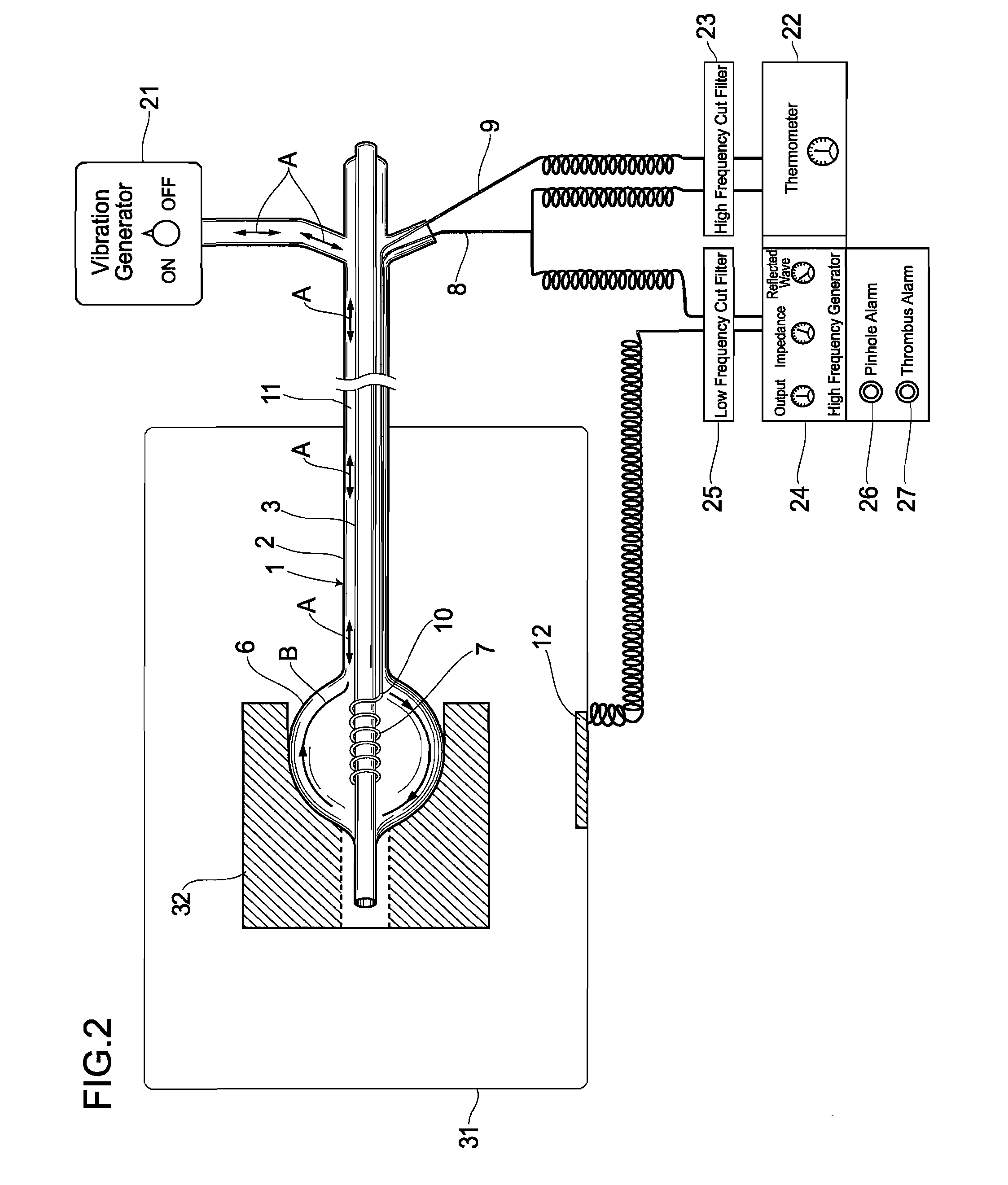
[0026]The structure of the radiofrequency thermal balloon catheter system of the present embodiment is described, with reference to FIG. 1 and FIG. 2.

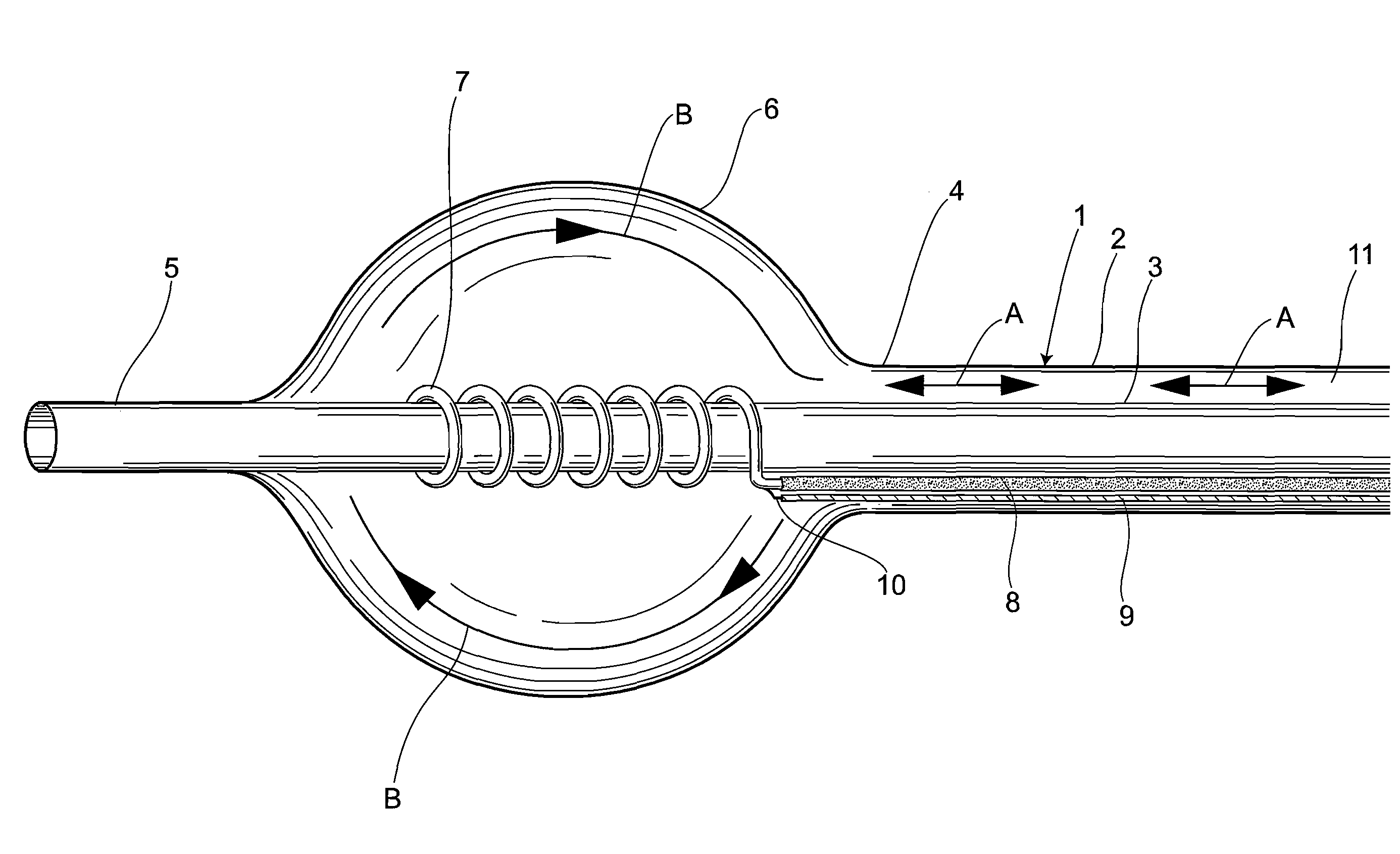
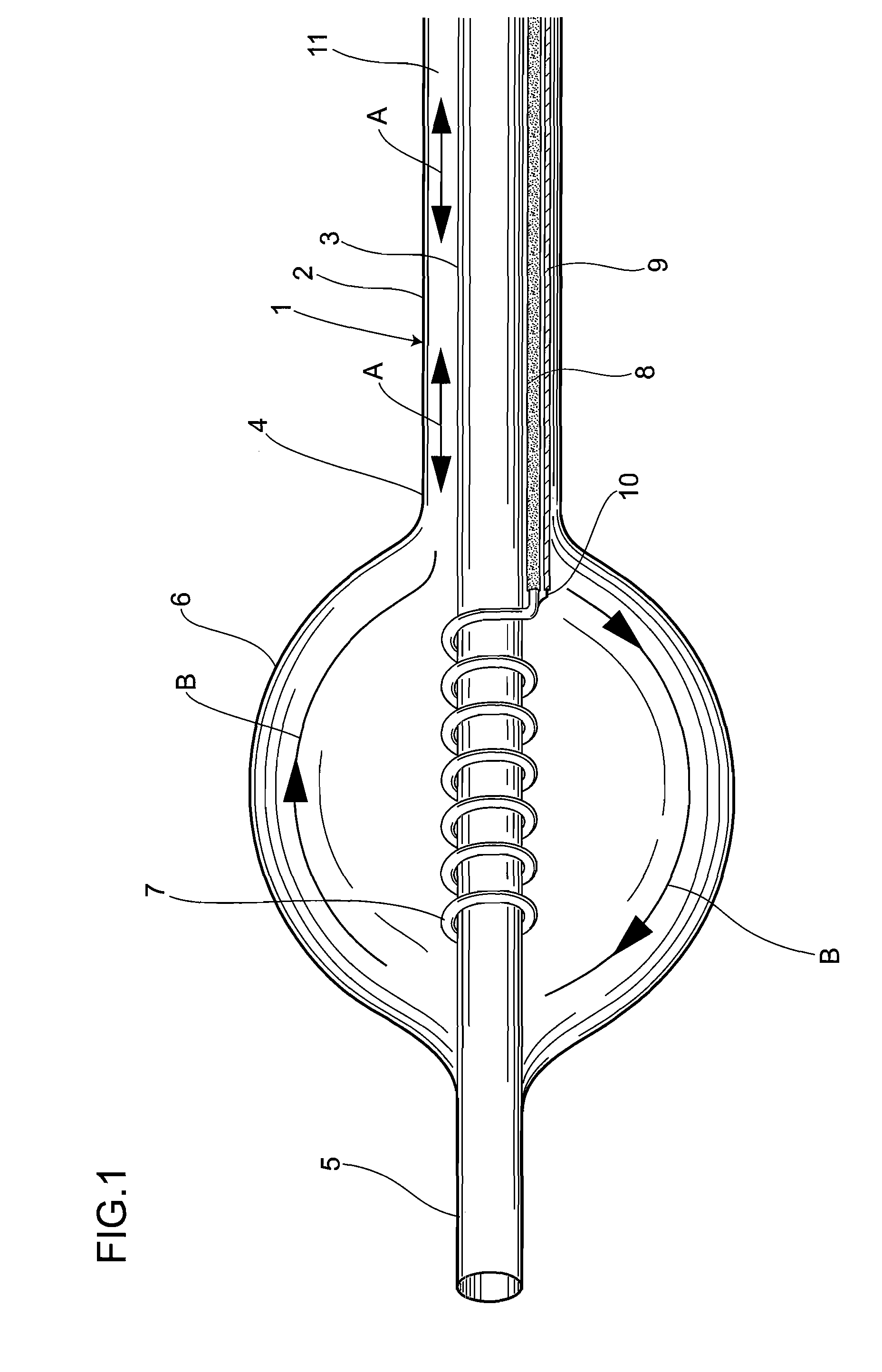
[0027]Reference symbol 1 denotes a catheter shaft. This catheter shaft 1 is composed of an outer tube 2 and an inner tube 3 which are slidable with each other. A balloon 6 is provided between a distal end 4 of the outer tube 2 and the vicinity of the distal end 5 of the inner tubes.

[0028]A coiled electrode 7 serving as a unipolar electrode for delivery of radiofrequency energy is provided inside of the balloon 6. Moreover, a radiofrequency transmission line 8 is connected to the coiled electrode 7. More specifically, the coiled electrode 7 is formed in a coil shape extending from the distal end of the radiofrequency transmission line 8, and is wound around the inner tube 7 inside of the balloon 6. In the present embodiment, the radiofrequency transmission line 8 is formed from a coated copper wire, and the coiled electrode 7 is formed ...

experimental example 1

[0054]The laboratory bath 31 was filled with a physiological salt solution at 37° C. to perform the experiment. The balloon was brought into contact with the phantom 32 in the physiological salt solution, and energized with a radiofrequency from the radiofrequency generator 24. Then, after about 100 seconds, the impedance, the output, the temperature of the center of the balloon 6, and the reflection waves were all in a steady-state. After 300 seconds from the start of energization, when a pinhole occurred in the balloon 6, although the output, the temperature, and the reflection waves slowly changed, the impedance was sensitively reacted and rapidly decreased.

experimental example 2

[0055]The laboratory bath 32 was filled with a heparinized whole blood solution at 37° C. to perform the experiment. The balloon was brought into contact with the phantom 32 in the whole blood, and energized with a radiofrequency from the radiofrequency generator 24, at a set temperature of 100° C. The temperature of the center of the balloon 6 was gradually increased, and when this exceeded 80° C. after about 300 seconds from the delivery of radiofrequency energy, a thrombus was formed on the surface of the balloon 6. Accompanying the thrombus formation, although the output, the temperature, and the reflection waves were slowly changed, the impedance was sensitively reacted and rapidly increased.


PUM


Abstract

A radiofrequency thermal balloon catheter system which is accurate in the detection temperature, capable of miniaturization compared to conventional systems, reliably detecting pinholes and adhesion of thrombi. A thermocouple is composed of a radiofrequency transmission line and a single metal wire joined to the distal end thereof. A coiled electrode is formed in a coil shape by extending the distal end of the radiofrequency transmission line. The distal end of the metal wire is brought into pin-point connection with the proximal end of the coiled electrode. A radiofrequency generator monitors the radiofrequency output, total impedance, and reflection waves, while supplying the coiled electrode and a counter electrode plate with a radiofrequency of 1 to 5 MHz, and automatically controls the radiofrequency output, so that the temperature of the coiled electrode can be kept at a target value.

Description

INCORPORATION BY REFERENCE[0001]The present application claims priority under 35 U.S.C. §119 to Japanese Patent Application No. 2007-004130 filed on Jan. 12, 2007. The content of the application is incorporated herein by reference in its entirety.BACKGROUND OF THE INVENTION[0002]1. Field of the Invention[0003]The present invention relates to a radiofrequency thermal balloon catheter system used for treatment of cardiovascular diseases.[0004]2. Description of Related Art[0005]A method is proposed by the present inventor in which, with respect to lesions such as an origin of arrhythmia or atherosclerosis, an electrode for delivery of radiofrequency energy is arranged inside an elastic balloon, and a radiofrequency electric field is radiated therefrom, to provide thermotherapy to a tissue in contact with the balloon, as is shown in: Japanese Unexamined Patent Publication No. 2005-177293; Japanese Unexamined Patent Publication No. 2004-223080; Japanese Patent Publication No. 2538375; Ja...

Claims


Application Information

Patent Timeline
Patent Type & Authority Applications(United States)
IPC IPC(8): A61B18/18
CPCA61B18/1492A61B2018/00023A61B2018/0019A61B2018/00214A61B2018/0022A61B2018/1437A61B2018/00779A61B2018/00785A61B2018/00821A61B2018/00875A61B2018/00702
Inventor SATAKE, SHUTARO
Owner JAPAN ELECTEL
Why Eureka
Try Eureka