System and method for the removal of undesired wavelengths from light

a technology of undesired wavelengths and light source, which is applied in the field of illumination, can solve the problems of light source generating wavelengths of light which are not useful for illumination, mild deterioration to complete loss of vision, and human eye damage, and achieves the effects of reducing undesired wavelengths in light, reducing the cost of operation, and being more durabl

Inactive Publication Date: 2008-07-24
ALCON INC
View PDF2 Cites 16 Cited by
  • Summary
  • Abstract
  • Description
  • Claims
  • Application Information

AI Technical Summary

Benefits of technology

[0007]Embodiments of the present invention provide an illumination system and method that can be utilized in conjunction with a surgical console and which are substantially safer, more durable and less expensive to operate than prior art systems and methods for providing illumination. One embodiment of the present invention includes a method for providing light to a source of illumination. The method can comprise the steps of: providing light from a light source wherein the light has two components, one component reflected from a mirror having a coating operable to reflect desired wavelengths of light and transmit undesired wavelengths and a second component provided directly from the light source (e.g. not reflected off the mirror). Other embodiments may provide other mirrors to further reduce the undesired wavelengths in the light provided through the source of illumination. For example, an additional coated mirror may be provided such that the light (e.g. both components) may be filtered using this mirror. One of these mirrors may be a hot mirror coated to reflect the desired wavelengths and transmit the undesired wavelengths.
[0008]By removing undesired wavelengths of light, such as those that fall outside the visible spectrum or certain wavelengths of blue-light, embodiments of the present invention provide the advantage that the lifetime and reliability of components within the optical path of an illuminator may be extended by reducing the amount of radiation absorbed by components within the optical path while simultaneously improving the performance of the illuminator by reducing spherical and chromatic aberrations. By reducing or eliminating such problems in the optical path, the safety of illumination systems incorporating an embodiment of the present invention, especially in a surgical context, may be greatly improved.

Problems solved by technology

The human eye can suffer a number of maladies causing mild deterioration to complete loss of vision.
In many cases, the light source may generate wavelengths of light which are not useful for illumination (e.g., those other than visible light), such as ultraviolet (UV) or infrared (IR) light.
These wavelengths may adversely affect the surgical system by, for example, causing a reduction in the lifetime of lamp electrodes, thermal and UV damage to the system optical components over time, decreased optical performance due to spherical and chromatic aberrations, beam steering, etc.
More specifically, the illuminator bulb electrodes, due to absorbing this undesired radiation, will erode more quickly, the optics of the system may heat up significantly leading to reliability issues (i.e. thermal shock and cracking) in the optics as well as their optical coatings, and thermal expansion can induce spherical and chromatic aberrations in the optics of the system, further reducing the performance of the system.
This is an undesirable effect because damage to the surgical system optics or their optical coatings can lead to a dangerous amount of light passing through the optics and into the eye, resulting in eye damage.
Furthermore, unwanted UV or IR radiation that reaches the eye can potentially cause eye damage.
However, no specific hardware or methods were put in place to eliminate undesired radiation at the illuminator optical source or from the optical train upstream of the hot mirror.
Thus, during the operation of these prior art systems the hot mirror and the optics upstream of the hot mirror continued to heat to unacceptable levels.

Method used


Image

  • System and method for the removal of undesired wavelengths from light
  • System and method for the removal of undesired wavelengths from light
  • System and method for the removal of undesired wavelengths from light

Examples


Embodiment Construction

[0015]Preferred embodiments of the invention are illustrated in the FIGURES, like numerals being used to refer to like and corresponding parts of the various drawings.

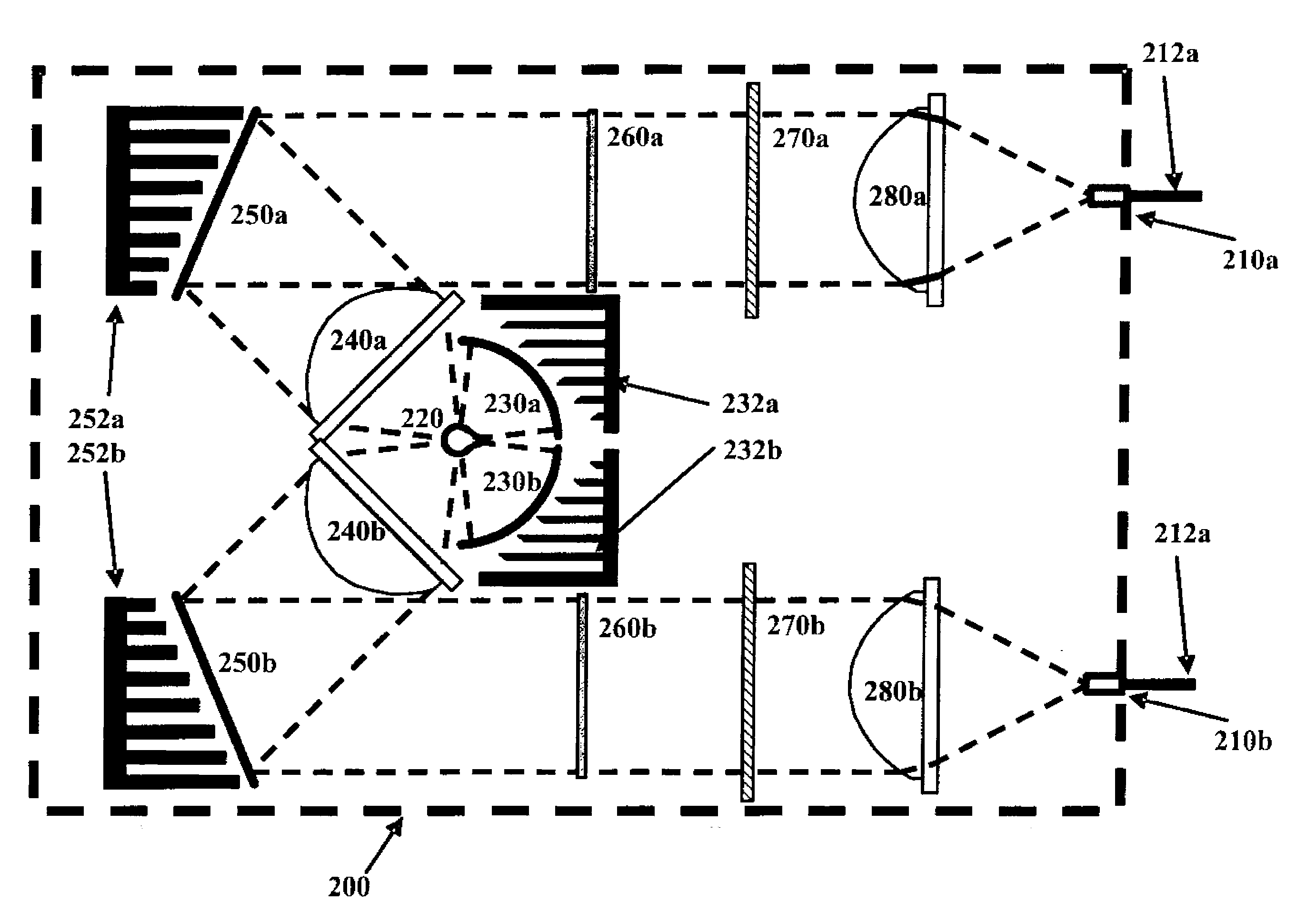
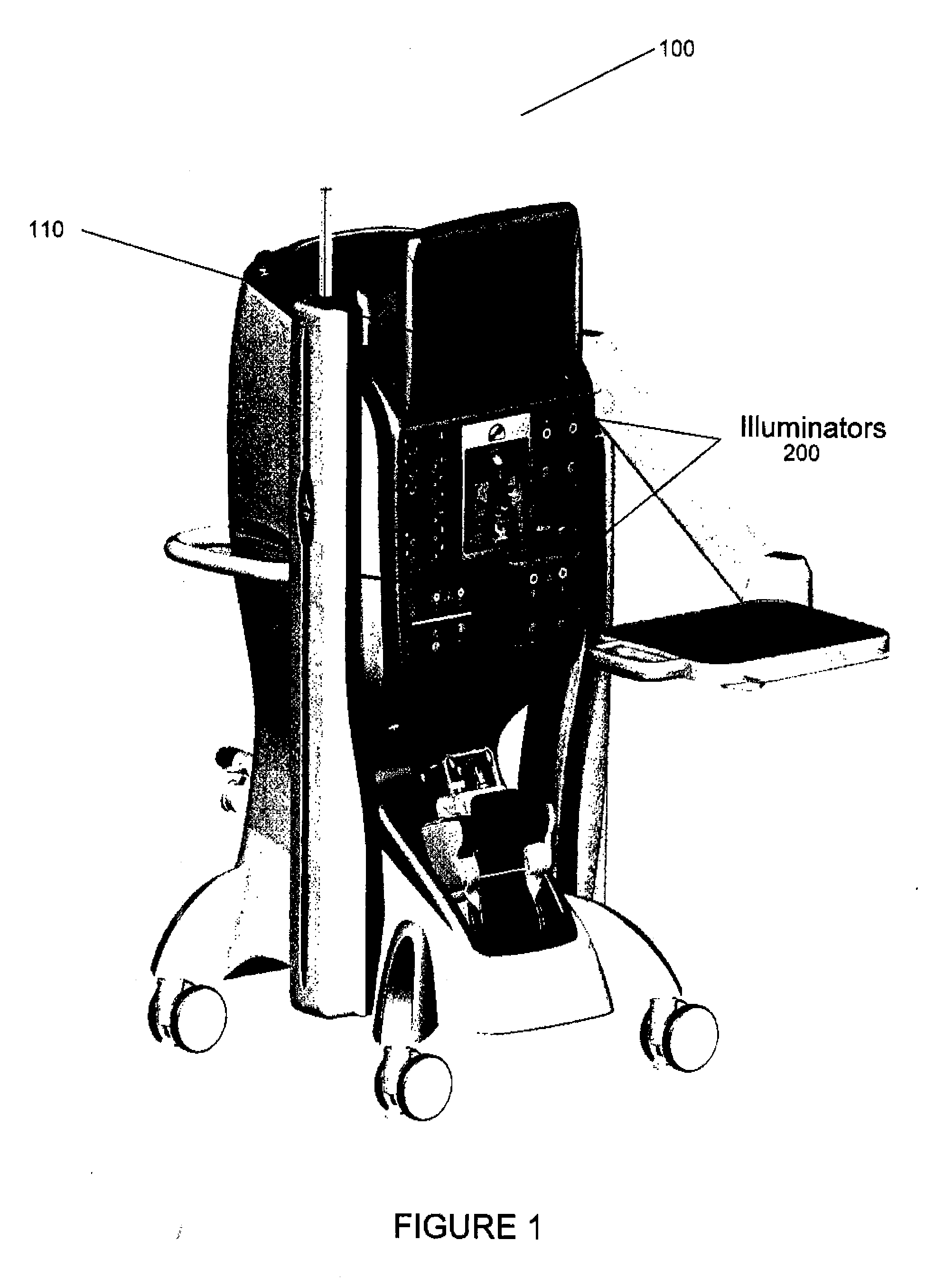
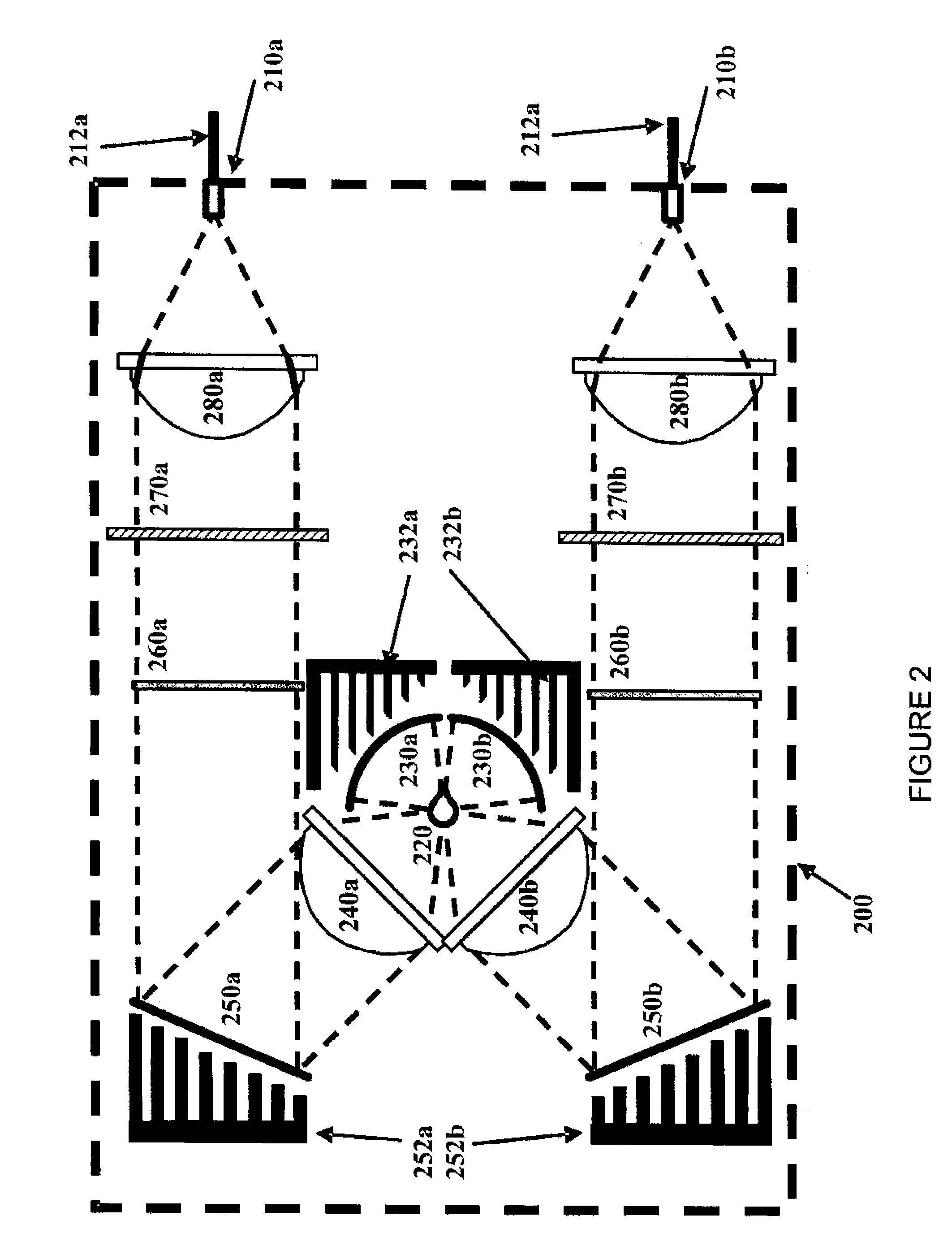
[0016]Vitreoretinal and Cataract microsurgical consoles can provide an illuminator. These illuminators provide visible light from a light source through, for example, an optic fiber or the like, and may be used to illuminate an area on which a procedure is being performed. The light source for these illuminators may generate wavelengths of light which are not useful for illumination (e.g., those other than visible light), such as ultraviolet (UV) or infrared (IR) light, or which may cause aphakic hazard weighted irradiance, such as certain wavelengths of blue light. These extraneous wavelengths may adversely affect the surgical system, including causing a reduction in the lifetime of certain components, decreased performance due to spherical and chromatic aberrations or other causes, etc. Damage to the optics or their ...


PUM


Abstract

Embodiments of the present invention provide a system and method for filtering light. More particularly, embodiments of the present invention may filter light provided as a source of illumination by using one or more mirrors in an optical path. In a specific embodiment, one or more cold mirrors in the optical path are coated such that they are operable to reflect light in the desired wavelengths while transmitting other wavelengths of light. Thus, as light from a light source is reflected off these cold mirrors undesired wavelengths of light may be substantially removed from the light before it is utilized to illuminate an area. In other embodiments, one or more hot mirrors mirror may also be provided in the optical path, where these hot mirrors are coated such that they are operable to transmit the desired wavelengths of light and reflect undesired wavelengths.

Description

TECHNICAL FIELD OF THE INVENTION[0001]The present invention relates to sources of illumination. More particularly, embodiments of the present invention relate to the removal of undesired wavelengths from light. Even more particularly, embodiments of the present invention relate to systems and methods for removing undesired wavelengths from light using mirrors.BACKGROUND[0002]The human eye can suffer a number of maladies causing mild deterioration to complete loss of vision. While contact lenses and eyeglasses can compensate for some ailments, ophthalmic surgery is required for others. Generally, ophthalmic surgery is classified into posterior segment procedures, such as vitreoretinal surgery, and anterior segment procedures, such as cataract surgery. More recently, combined anterior and posterior segment procedures have been developed.[0003]The surgical instrumentation used for ophthalmic surgery can be specialized for anterior segment procedures or posterior segment procedures or s...

Claims


Application Information

Patent Timeline
Patent Type & Authority Applications(United States)
IPC IPC(8): G02B5/08F21V9/00
CPCA61B19/52A61B19/5202A61F9/007G02B5/208G02B27/145G02B6/0006G02B27/1006G02B27/143G02B5/286A61B90/30A61B90/36
Inventor PAPAC, MICHAELBUCZEK, MARKSMITH, RONALDARTSYUKHOVICH, ALEX N.DACQUAY, BRUNO
Owner ALCON INC
Why Eureka
Try Eureka