Wavelength converting structure and manufacture and use of the same

a technology of wavelength conversion and structure, applied in the direction of instruments, discharge tube luminescnet screens, synthetic resin layered products, etc., can solve the problems of low production yield, difficult to produce large-sized lamps and allow wavelength conversion in large areas, and substantial increase in costs

Inactive Publication Date: 2008-07-24
KISMART
View PDF0 Cites 27 Cited by
  • Summary
  • Abstract
  • Description
  • Claims
  • Application Information

AI Technical Summary

Benefits of technology

[0033]After reviewing the embodiments described below, persons having ordinary skill in the art can easily appreciate the basic spirit a...

Problems solved by technology

However, the phosphor coating and the light emitting source have to be disposed in the same vacuum lamp tube, and thus, it is difficult to produce large-sized lamps and allow for wavelength conversions in large areas.
Moreover, if a larger light emitting area is obtained by lengthening the lamp tube, there are some disadvantages such as low production yields and a substantial increase in costs.
However; the limitations in application still exist with the EEFLs.
As a result, there will be poor heat dissipation.
Moreover, just like the CCFL, the EEFL also cannot provide a larger light emitting area.
Unfortunately, the LED still has some shortcomings, such as color mixing inaccuracies, high manufacturing costs, inferior uniformity, poor heat dissipation, and low power efficiency.
Although the CNT has advantages, such as low power consumption, low temperature operation, and lack of Hg, the CNT still presents some problems due to its complicated manufacturing process, high cost, poor brightness...

Method used


Image

  • Wavelength converting structure and manufacture and use of the same
  • Wavelength converting structure and manufacture and use of the same
  • Wavelength converting structure and manufacture and use of the same

Examples


example 1

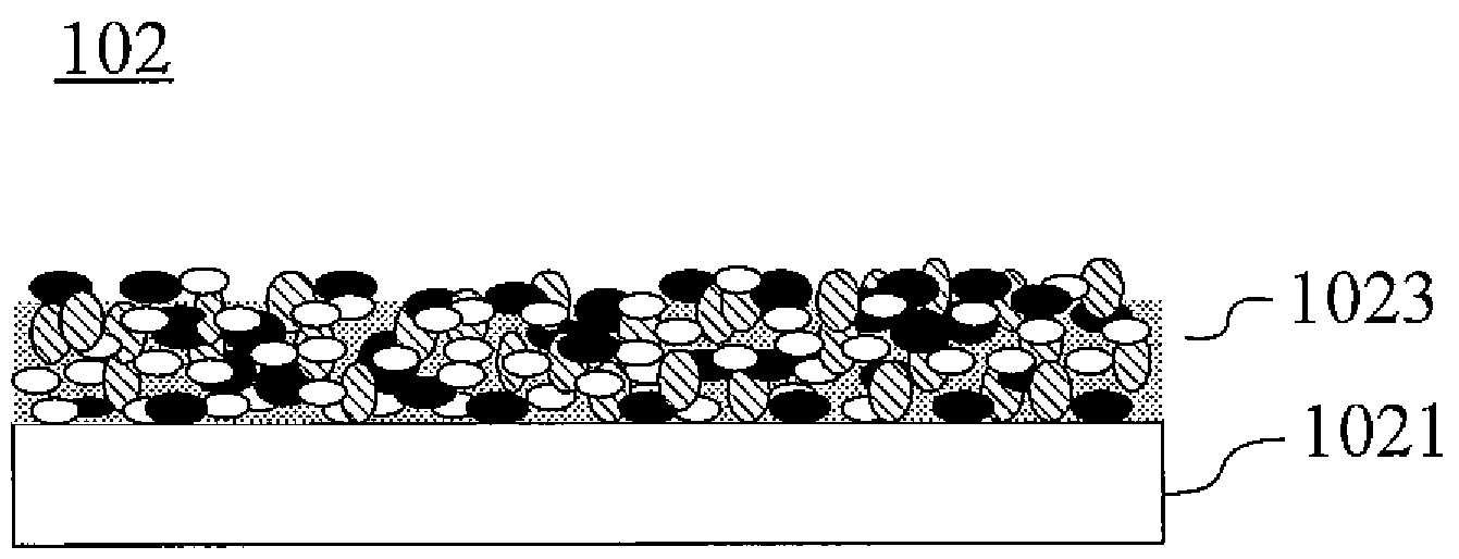
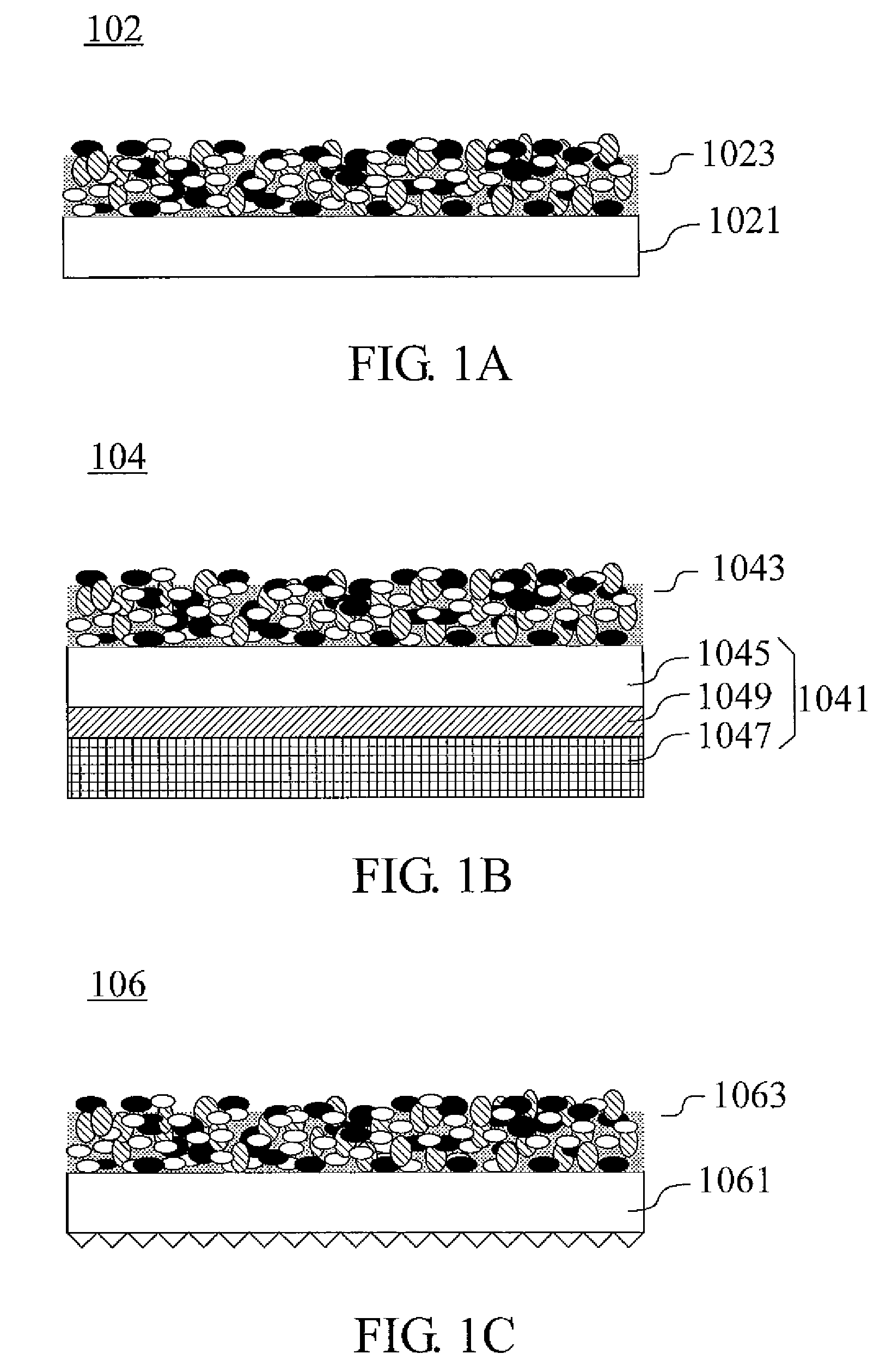
[0130]900 g of the adhesive solution A was put into a 2000 ml beaker and stirred by a magnet for 10 mins. Then, 900 g of phosphor powder was added thereto, and the mixture was stirred by a mechanical impeller for 20 mins at room temperature to get a homogeneously mixed slurry. Once mixed homogeneously, the slurry was put into an air pressure type pulsing circulator for stirring for 30 mins before being coated onto a PET substrate (125 μm in thickness) by a slot coating method. During slot coating, the film was coated with a coating pressure of 0.12 MPa and a speed of 15 cm / min, with the coating slot being spaced 15 μm from the PET substrate. The resulting wet film was then dried with a hot air at 50° C., thus obtaining a sample that had a wavelength converting coating of 12 to 15 μm in thickness on the PET substrate.

[0131]The brightness testing method I was adopted, where the area for placing the sample was in a size of 30 cm in length and 20 cm in width and the sample was 1.5 cm aw...

example 2

[0133]The slurry preparation, coating and drying steps of Example 1 were repeated, except that the slurry was coated onto a PET substrate of 125 μm in thickness to obtain a sample that had a wavelength converting coating of 12 to 15 μm in thickness on the PET substrate.

[0134]Subsequently, using a scraper, an acrylic-based adhesive from PANTECH TAPE CO., Ltd. (No. S3277) was coated onto the other side of the sample to achieve a thickness of 25 μm. Then, the sample was laminated with an acrylic-based substrate (2 cm in thickness) and a PET protection substrate (25 μm in thickness) together by a roll laminator from CSUN MEG. Ltd. (No. CSL-M25R). Thus, the adhesive side of the sample was laminated onto one side of the acrylic-based substrate while the PET protection substrate was laminated onto the other side of the acrylic-based (polymethyl methacrylate) substrate. The laminating process was carried out at a speed of 1.5 m / min with a pressure of 3 kgf / cm2 at 40° C. Similarly, the above...

example 3

[0136]A metered amount of phosphor powder and a metered amount of adhesive solution were formulated into mixtures with the weight ratios listed in Table 3, respectively. The mixtures were then put into six 50 ml sealed vials respectively to be stirred therein by a magnet for 10 mins, followed by an ultrasonic oscillation for another 10 mins to obtain six slurries.

[0137]A PET substrate (125 μm in thickness) sized 10 cm in width and 15 cm in length was adsorbed onto a vacuum adsorption table and was coated with one of these slurries by a meyer rod coating approach with a coating speed of 10 m / min. Such a coating process was repeated for the six slurries to obtain six PET substrates coated with individual slurries, which were then subjected to a natural drying process through air circulation for 3 mins to finally obtain coatings in a thickness of about 15 to 18 μm.

[0138]The brightness testing; method I was adopted, where the area for placing the sample had a size of 30 cm in length and...


PUM

PropertyMeasurementUnit
Fractionaaaaaaaaaa
Fractionaaaaaaaaaa
Percent by volumeaaaaaaaaaa

Abstract

A wavelength converting structure is provided. The wavelength converting structure comprises the following:
a substrate, and
a wavelength converting coating which is deposited on the substrate and comprises:
(a) a phosphor powder which can be excited by UVC; and
    • (b) an anti-UVC adhesive,
wherein the thickness of the wavelength converting coating is 2 to 10 times the average particle size of the phosphor powder and the amount of the phosphor powder in the wavelength converting coating conforms to at least one of the following requirements:
(i) the phosphor powder should be about 30% to 85% by volume of the wavelength converting coating based on the total volume of the phosphor powder and the adhesive; and
(ii) the weight ratio of the phosphor powder to the adhesive should range from 1:1 to 20:1.
The wavelength converting coating can effectively convert UVC to visible light to provide a visible light source with a high surface area.

Description

[0001]This application claims priorities to Taiwan Patent Application No. 096102110 filed on Jan. 19, 2007 and Taiwan Patent Application No. 096127149 filed on Jul. 25, 2007.CROSS-REFERENCES TO RELATED APPLICATIONS[0002]Not applicable.BACKGROUND OF THE INVENTION[0003]1. Field of the Invention[0004]The subject invention relates to a wavelength converting structure. More particularly, the invention relates to a structure comprising a wavelength converting coating that can convert ultraviolet rays with a wavelength of no more than 280 nm (i.e. UVC) into a visible light. The coating may be used in conjunction with a UVC light source to convert a UVC wavelength into a visible light wavelength in the presence of air. The steps for manufacturing the wavelength converting structure are simple. Likewise, a flat light source with a large emitting area can be made in simply as well. Additionally, the subject invention further relates to the application of the wavelength converting structure in...

Claims


Application Information

Patent Timeline
IPC IPC(8): B32B27/18B05D3/02C09K11/02H01L33/44H01L33/50H01L33/58
CPCC09K11/02Y10T428/265H01J1/68H01J1/64C09K11/08B82Y20/00G02F1/1335
Inventor CHANG, WEN-CHILIN, YU-PINGWANG, FU-TIENCHEN, CHIH-YUANCHEN, DING-HE
Owner KISMART
Why Eureka
Try Eureka