Cochlear implant device, extracorporeal sound collector, and cochlear implant system having the same

a cochlear implant and extracorporeal technology, applied in the field of cochlear implant devices, extracorporeal sound collectors, cochlear implant systems, can solve the problems of limited strength of the magnet used for attachment, the cochlear implant system feels while being used, and the inability to meet the needs of users, so as to improve the daily life of users of the cochlear implant system and extend the communication distance with the extracorporeal sound collector.

Inactive Publication Date: 2008-07-24
SEMICON ENERGY LAB CO LTD
View PDF30 Cites 32 Cited by
  • Summary
  • Abstract
  • Description
  • Claims
  • Application Information

AI Technical Summary

Benefits of technology

[0022]As described above, the cochlear implant device of the present invention includes a battery which is a self-driving power source that is not originally included in the device. Furthermore, a method of communication with the extracorporeal sound collector is not limited to being an electromagnetic coupling method, and a communication distance with the extracorporeal sound collector can be extended

Problems solved by technology

However, there are some major problems with the cochlear implant system in the wearing of a headpiece.
For example, one problem is with how the headpiece feels while it is being used.
In the case of wearing a headpiece, the strength of a magnet that is used for attachment is limited.
Although some of the hair over which the headpiece is attached need not be shaved off, when the headpiece is placed over the hair, the headpiece is unstable depending on the amount of hair.
Therefore, the headpiece cannot be worn properly depending on the hairstyle and the thickness of the skin.
Furthermore, there is a case in which unnatural discomfort occurs due to attachment while the headpiece is worn and a case in which a hairstyle cannot be chosen freely.
In addition, a speech processor which is used by being worn on an ear may be broken because of moisture from sweat, hair,

Method used


Image

  • Cochlear implant device, extracorporeal sound collector, and cochlear implant system having the same
  • Cochlear implant device, extracorporeal sound collector, and cochlear implant system having the same
  • Cochlear implant device, extracorporeal sound collector, and cochlear implant system having the same

Examples


embodiment mode 1

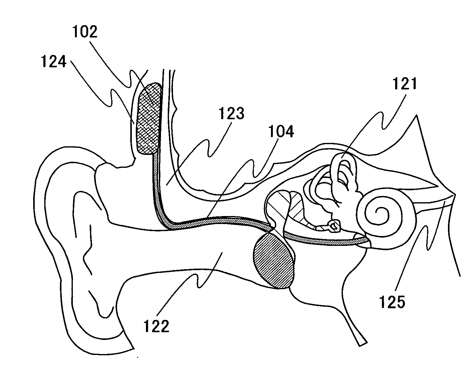
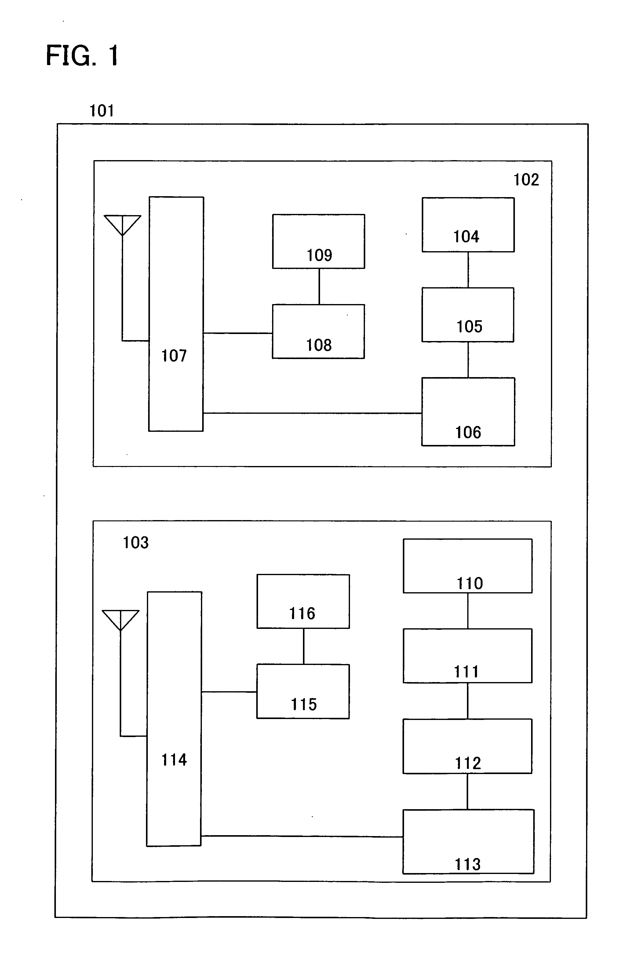
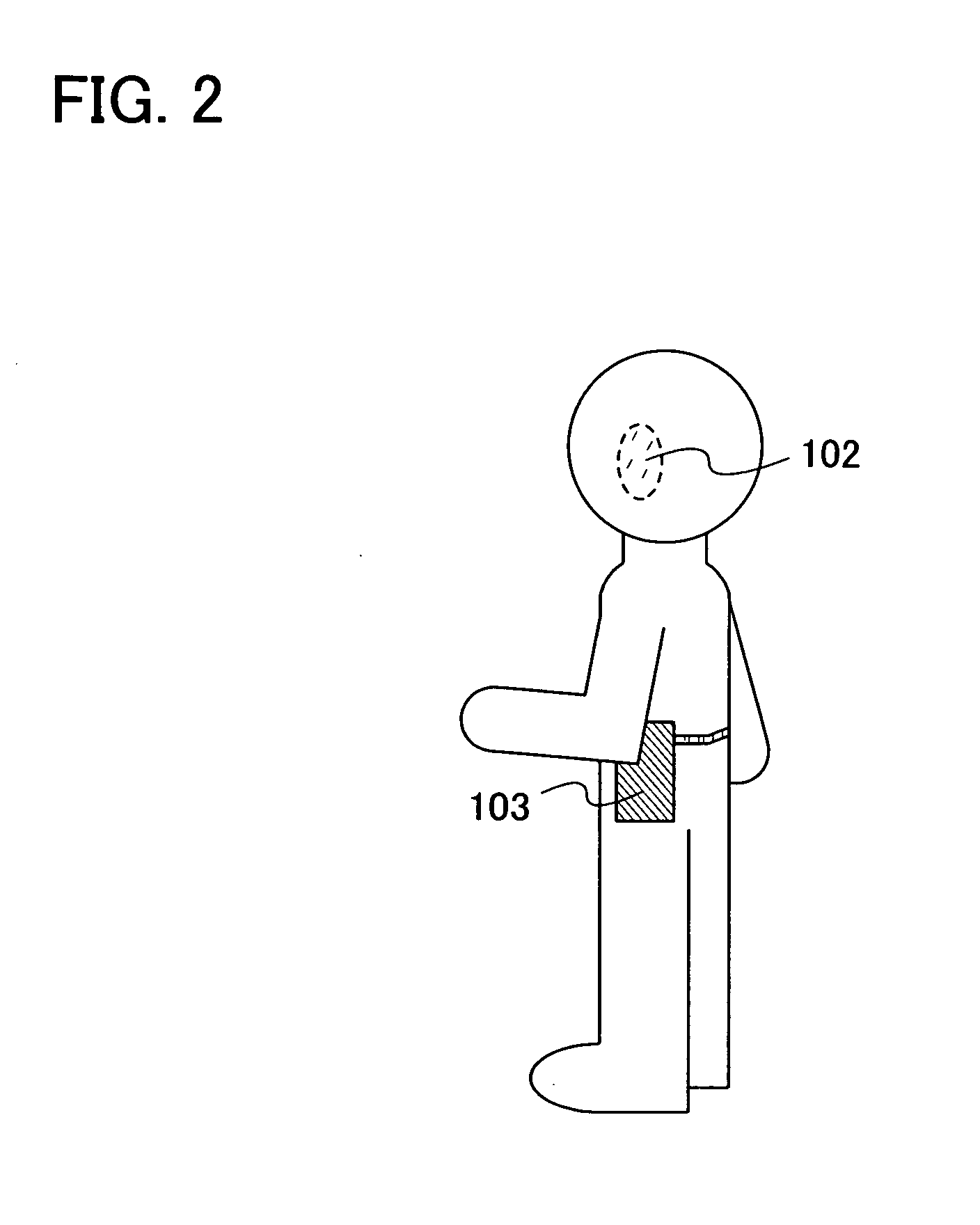
[0034]In this embodiment mode of the present invention, a cochlear implant device, an extracorporeal sound collector, and a cochlear implant system having each of them will be described. A cochlear implant system 101 of the present invention includes a cochlear implant device 102 which is embedded in a body and transmits information for sounds to an auditory nerve, and an extracorporeal sound collector 103 which detects ambient sounds from outside the body and transmits them to the cochlear implant device (see FIG. 1).

[0035]First, the cochlear implant device 102 will be described. The cochlear implant device 102 of the cochlear implant system 101 includes an inner ear electrode 104, an amplifier circuit 105, a central arithmetic processing circuit 106, a transmitter / receiver circuit 107, a charging circuit 108, and a battery 109.

[0036]The inner ear electrode 104 provides electric stimulation to the auditory nerve of an inner ear. The amplifier circuit 105 amplifies a signal that is ...

embodiment mode 2

[0056]In this embodiment mode, an example is shown in which the cochlear implant system 101 is used by use of a function included in the extracorporeal sound collector 103 of the present invention.

[0057]The extracorporeal sound collector 103 of the present invention includes the external input circuit 111. A radio, a cellular phone 200, a music player, or the like is connected to this external input circuit 111 so that a user of the cochlear implant system 101 can hear sounds outputted from the connected device (see FIG. 4).

[0058]For example, when information for sounds input from the outside is an analog signal, a structure can be used in which the external input circuit 111 is provided between the microphone 110 and the amplifier circuit 112. When information for sounds is input by a digital signal, a structure can be used in which the external input circuit 111 and the central arithmetic processing circuit 113 are connected to each other. Needless to say, a structure correspondin...

embodiment mode 3

[0061]In this embodiment mode, an example of a method for manufacturing the cochlear implant device described in Embodiment Modes 1 and 2 will be described with reference to FIGS. 1, 6A to 6D, 7A and 7B, 8A and 8B, 9A and 9B, and 10A and 10B. Although the cochlear implant device can be formed of a field effect transistor by use of a semiconductor substrate or an SOI substrate, a structure in which an antenna, a charging circuit, and a transmitter / receiver circuit are provided over the same substrate will be described in this embodiment mode. In addition, an example of a method for manufacturing a charging circuit and a transmitter / receiver circuit by use of a thin film transistor will be described. Note that an antenna, a charging circuit, a transmitter / receiver circuit, a central arithmetic processing circuit, an amplifier circuit, and the like can be formed over a substrate and thin film transistors as transistors included in the antenna, the charging circuit, the transmitter / rece...


PUM


Abstract

An object is to provide a cochlear implant system (also known as an artificial inner ear system) which is easy to use with little interference with daily activities. A cochlear implant device (or artificial inner ear device) includes an inner ear electrode, an information processing circuit, a transmitter/receiver circuit, a charging circuit, and a battery; and the battery is charged with electromagnetic waves received by the transmitter/receiver circuit through the charging circuit. In addition, the power stored in the battery is supplied to the cochlear implant device. Further, the electromagnetic waves received by the transmitter/receiver circuit are converted into a signal by the information processing circuit, and the signal is provided from the inner ear electrode to stimulate the auditory nerve.

Description

BACKGROUND OF THE INVENTION[0001]1. Field of the Invention[0002]The present invention relates to a cochlear implant device, an extracorporeal sound collector, and a cochlear implant system having each of them.[0003]2. Description of the Related Art[0004]A cochlear implant system is a device by which an electrical signal is directly applied to an inner ear (a cochlea) to make a brain perceive sound. The cochlear implant system has a structure formed of two main parts: a speech processor (referred to as an extracorporeal sound collector in this specification) and an inner ear electrode (referred to as a cochlear implant device in this specification). The speech processor (extracorporeal sound collector) converts a detected external sound into an electrical signal and transmits it to the inner ear electrode (cochlear implant device). The inner ear electrode (cochlear implant device) which receives the electrical signal is to provide a stimulus from an electrode inserted inside a cochle...

Claims


Application Information

Patent Timeline
IPC IPC(8): A61N1/00A61F2/18
CPCA61N1/0541A61N1/36032H01L27/13H01L27/1266H01L27/1214H01L27/1277A61N1/36038
Inventor HIROTA, TAKASHIYAMAGUCHI, MAYUMI
Owner SEMICON ENERGY LAB CO LTD
Why Eureka
Try Eureka