Taking distance images

a technology of distance images and distance measurement, applied in the field of distance images, to achieve the effects of increasing sensitivity, increasing measuring speed, and increasing rang

Active Publication Date: 2008-08-07
TRIPLE IN HLDG
View PDF6 Cites 59 Cited by
  • Summary
  • Abstract
  • Description
  • Claims
  • Application Information

AI Technical Summary

Benefits of technology

[0042]It is the object of the invention to set forth a possibility with which the said disadvantages of the prior are of current pulse TOF sensors for image talking can be overcome. The cutting of the effort in material and time for the considerable increase in sensitivity, the i

Problems solved by technology

The time measurement circuits or parts thereof are configured in a number of cases as an integrated “time measurement IC” due to the required switching speeds and complexity.
Existing sensors are generally limited in their speed of taking the measured value by the maximum pulse repetition rate of the laser modules used.
This is very slow in comparison with purely imaging sensors such as CCD cameras and is not suitable for the detection of dynamic processes within the spatial angle taken.
However, the technical effort is enormous because the conversion rate has to be at some GHz and the computing effort for the averaging is necessarily proportional thereto.
For this reason, sensors of this type have not achieved any importance in the market so that the sensitivity limit of today's pulse TOF sensors is generally larger than/equal to 4.5 NEP.
It is therefore a disadvantage of the prior art thatthe sensitivity (minimal signal-to-noise ratio) is limited to larger than/equal to 4.5 NEP since no noise pulses may be detected because they would be confusable with echo pulses and would falsify the result;only one echo pulse, in rare cases two echo pulses, can be processed during the TOF and so reflections from rain, snow, fog or from the dirty termination glass of the sensor or from a plurality of impacted targets cannot be evaluated within a TOF or even make the measurement impossible, so that external applications for pulse TOF sensors can only be realized with great limitations;no parallel processing of a plurality of signal pulses or parts of a signal pulse is possible;no larger number of pulses such as noise pulses which generally occur increasedly at a low selection of the comparator threshold during the TOP can be measured with existing time measurement circuits;no 2D distance image taking (profile) is possible without a scanner with movable mirrors;a 3D distance image talking is only possible with two scanners with movable mirrors;no sufficient speed for a 2D or a 3D distance image talking can be achieved.
Only very small ranges can be achieved with these sensors with a very large power and averaging effort so that t

Method used


Image

  • Taking distance images
  • Taking distance images
  • Taking distance images

Examples


Embodiment Construction

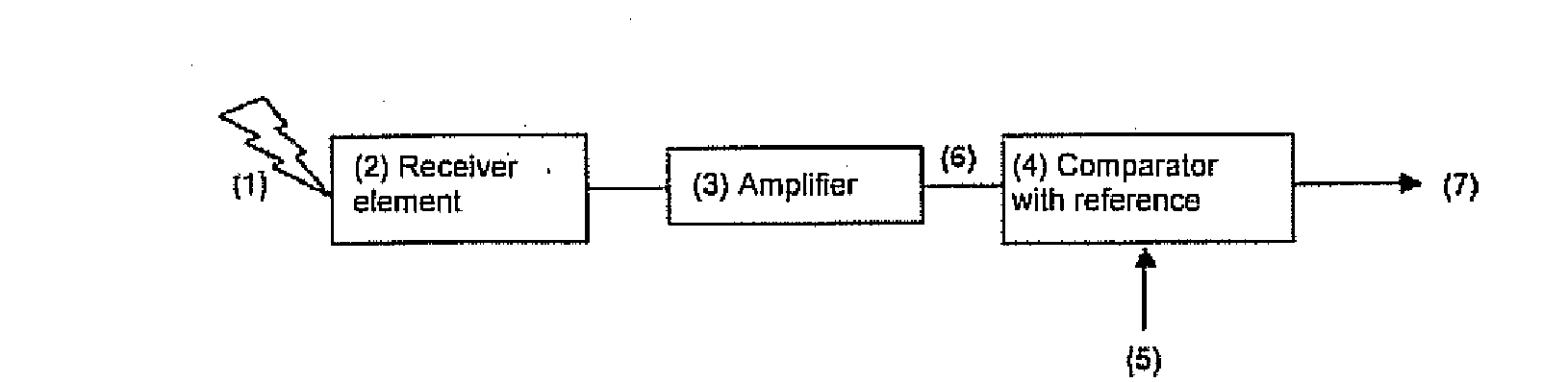
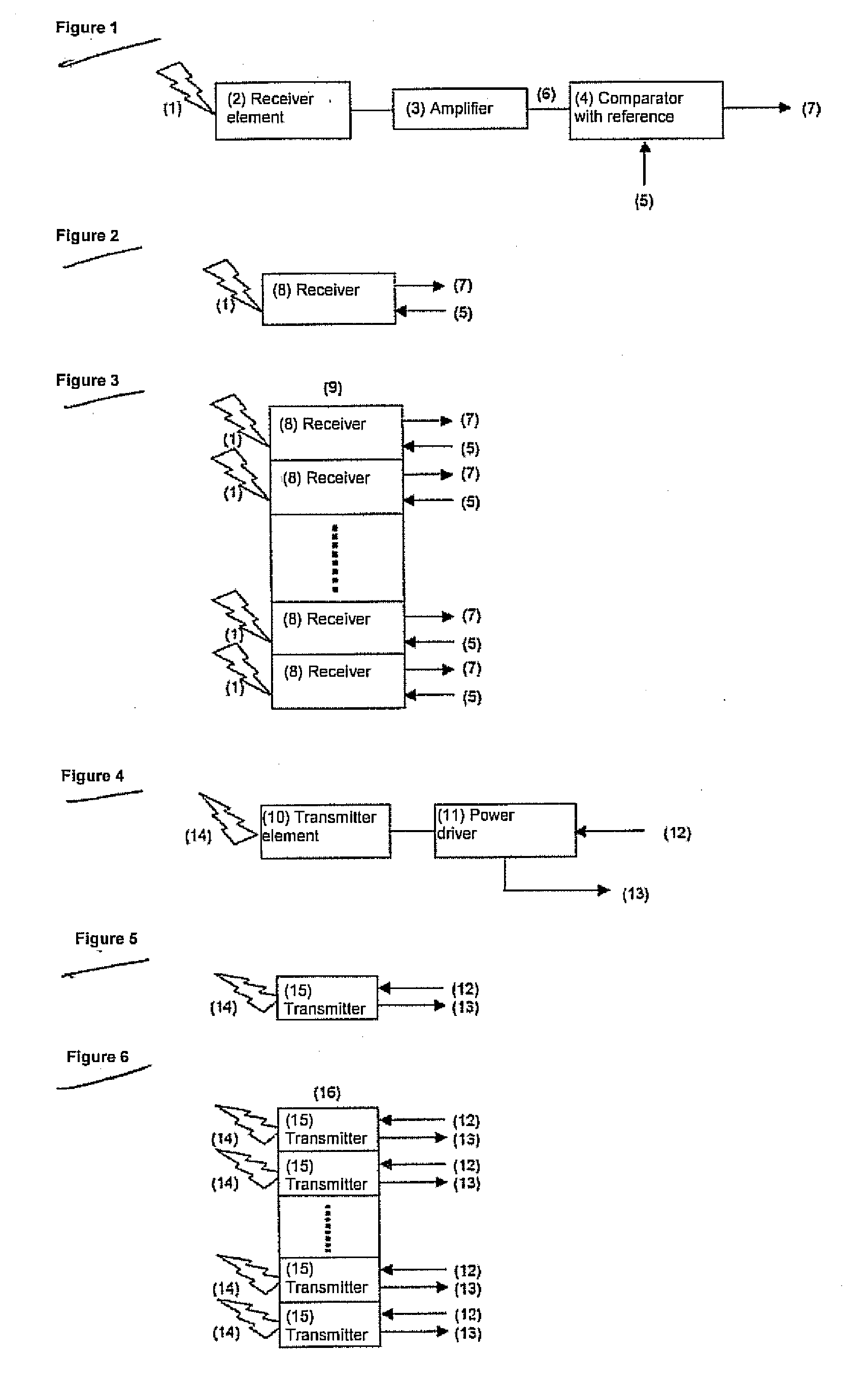
[0092]FIG. 1 shows the basic structure of a receiver comprising an APD (2) with which the optical pulses (1) reflected from a target and received via a receiving lens as a converging radiation system (48) (cf. FIGS. 12a, 21-23) are converted into electrical signals, followed by a broadband amplifier (3) and a comparator (4) with the adjustable reference (5) and the digitized output signal (7).

[0093]The elements of the receiver are assembled in FIG. 2 to form a receiver module (8). The module (8) has the digitized output signal (7) and the reference (5).

[0094]In FIG. 3, the receiver modules (8) from FIG. 2 are assembled to form a receiver array (9) and deliver the input signals (7) for the time measuring channels. If only one laser beam (14) from one laser (10) is present, part rays of an optical pulse (1) reflected by the receiver array (9) are detected. If a plurality of lasers (10) transmit an array of laser beams, then part arrays of the receiver array (9) each detect the beam of...


PUM


Abstract

The invention relates to a method for the taking of a large number of distance images comprising distance picture elements, wherein electromagnetic radiation is transmitted in each case in the form of transmission pulses using a plurality of transmitters arranged in an array for each distance image to be taken and reflected echo pulses are detected using a plurality of receivers arranged in an array, with the respective distances of objects at which the transmission pulses are reflected and forming a distance picture element being measured by determining the pulse time of flight, wherein a plurality of individual measurements are carried out using a time measuring device connected after the receiver array for each distance image to be taken, in which individual measurements a respective pulse chain is processed which includes a logical start pulse derived from the respective transmission pulse and at least one logical receiver pulse formed from an echo pulse or a noise pulse, wherein the logical receiver pulses are each generated by means of at least one reference of the receiver, the reference being broken through by the underlying echo pulses or noise pulses, with an exceeding of the reference forming the positive flank of the receiver pulse defining an up event and a falling below of the reference forming the negative flank of the receiver pulse defining a down event, wherein, for each distance image to be taken, the associated pulse chains are formed in that the start pulses and the associated receiver pulses are each combined at the right time, the pulse chains formed in this manner are distributed over an array of time measuring channels formed by the time measuring device in accordance with a pre-settable measurement procedure, and, for each time measuring channel, the time durations are determined which, in each case with reference to a point in time before the start pulse, pass until a receiver pulse in that, for each up event and/or for each down event, at least the respective clock pulses are counted which are made available by a central clock at a known frequency, and the counter results are stored as an event list in an arrangement taking account of their respective time information, and wherein the stored event lists of all time measuring channels are read out and evaluated in order to convert the respective time information contained in the event lists into distance values corresponding to the distance picture elements.

Description

CROSS-REFERENCE TO RELATED APPLICATIONS[0001]This application claims priority of European Patent Application No. 06 019 388.5 filed Sep. 15, 2006.FIELD OF THE INVENTION[0002]The invention relates to a method and to an apparatus for the taking of distance images comprising a large number of distance picture elements in accordance with the independent claims 1 and 34. The invention furthermore relates to an IC module having a time measuring device in accordance with claim 64 for the carrying out of the method in accordance with the invention and / or for the apparatus in accordance with the invention.BACKGROUND OF THE INVENTION[0003]“Distance images” are here not only to be understood as two-dimensional arrangements of distance picture elements, but also one-dimensional arrangements, also called profiles, i.e. distance images which each include a single row of distance picture elements disposed next to one another.[0004]It is the object in distance measurement to measure the time betwee...

Claims


Application Information

Patent Timeline
IPC IPC(8): G01C3/08G01S17/89G01S7/4865
CPCG01S7/481G01S7/4815G01S17/89G01S7/4865G01S7/487G01S7/4817
Inventor HIPP, JOHANN
Owner TRIPLE IN HLDG
Why Eureka
Try Eureka