
Interference Apparatus And Method And Probe

a technology interferometer, which is applied in the field of optical coherence tomography apparatus and methods and probes, can solve the problems of limited acquisition speed, poor signal-to-noise performance, and inability to dynamically adjust focus for best lateral resolution

Active Publication Date: 2008-08-14
MICHELSON DIAGNOSTICS
View PDF19 Cites 96 Cited by
  • Summary
  • Abstract
  • Description
  • Claims
  • Application Information

AI Technical Summary

Benefits of technology

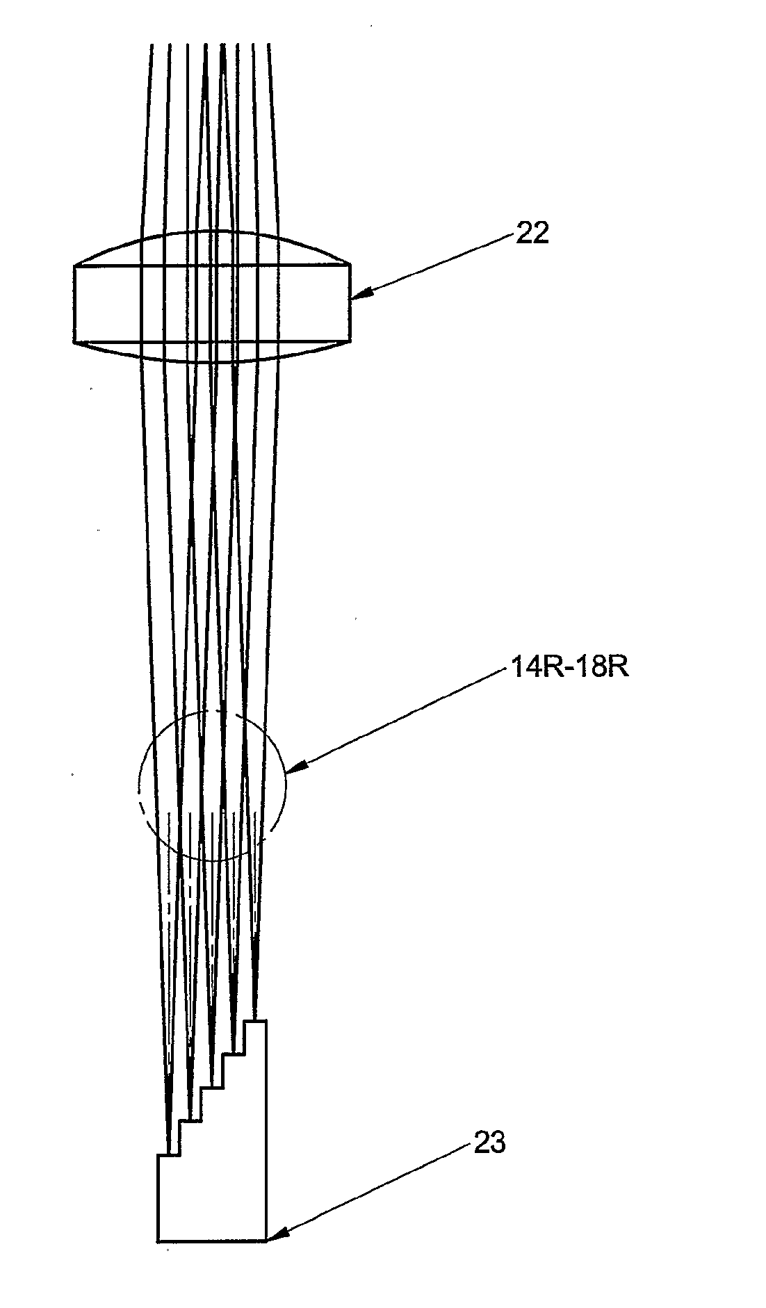
[0021]Thus, each interferogram provides an A-scan image which is only in sharp focus over a limited depth range (the depth of focus, also known as the Rayleigh range), but by combining these images for a plurality of different focal depths, a single A-scan image may be constructed with an increased depth of field.
[0025]To perform a B scan, it is necessary to relatively scan the beams and the surface being examined, and thus a scan means is provided. Usually a scan means is provided for scanning the beams along a line across the surface of the substance being examined. For a convenient optical design, it is desirable for the plurality of beams to be spaced along the scan line to a small extent. This leads to the information for different depth ranges at a given location arriving at slightly different times during the lateral scan, rather than simultaneously, an effect which has to be compensated for in assembling the combined image.
[0028]The probe preferably comprises a probe shaft, and a handle is preferably provided at the proximal end of the probe shaft, and preferably the scanner is mounted within the handle. The probe shaft may be detachable from the handle for cleaning (the probe shaft would normally be used within a disposable sheath however). Note that it is preferable to constrain the shaft to a specific orientation, so that any internal baffles which may be fitted within the shaft, or lens tilts to eliminate reflections, will align correctly with the scan direction. Because the scanner is not within the probe shaft itself, different variants of probe shaft may conveniently be provided, mating to the common handle, allowing different lengths of probe shaft, and probe shafts with angled views. If the length of the optical measurement path through the probe shaft is altered, a corresponding compensation in the reference path will be required.

Problems solved by technology

Time domain OCT (the original, and currently the most prevalent, type) is limited in acquisition speed by the need for mechanical depth scanning, and has relatively poor signal-to-noise performance.
In contrast, Fourier domain OCT acquires information from the whole depth at the same time, so it is not possible to dynamically adjust focus for best lateral resolution.
There are three main difficulties in providing a practical arrangement of an OCT probe in which the conflicting optical and medical requirements are resolved.
Firstly, there are difficulties in obtaining an image which is suitably in focus over the depth of the (A scan) image.
Secondly, to provide a B-scan image it is necessary to scan laterally across the surface.
This approach has the disadvantage of placing moving parts, and the power to drive them, inside the patient's body, and may increase the difficulty of sterilizing the equipment.

Method used


Image

  • Interference Apparatus And Method And Probe
  • Interference Apparatus And Method And Probe
  • Interference Apparatus And Method And Probe

Examples


Embodiment Construction

General Description

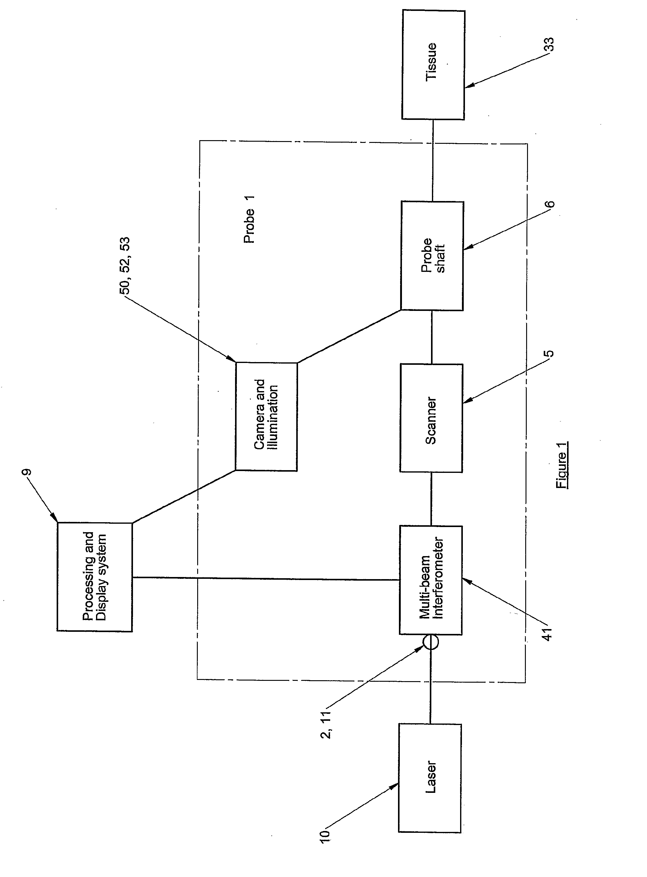
[0055]FIG. 1 shows a block diagram of the OCT apparatus indicating a laser 10, provided usually remotely from the probe 1, but in some circumstances within the probe 1. A laser beam 11 from the laser 10 is passed to the probe, usually through a single-mode optical fibre 2. The laser 10 provides a swept spectrum over a wavelength range of at least 50 nm, within a region of the infra-red where tissue absorption is minimised. A wider spectrum improves the depth resolution. The probe 1 comprises a multi-beam interferometer 41, a scanner 5, a probe shaft 6 and camera with illumination system 50, 52, 53, and other components detailed below. The processing and display system 9 and tissue under examination 33 are external to the probe 1.

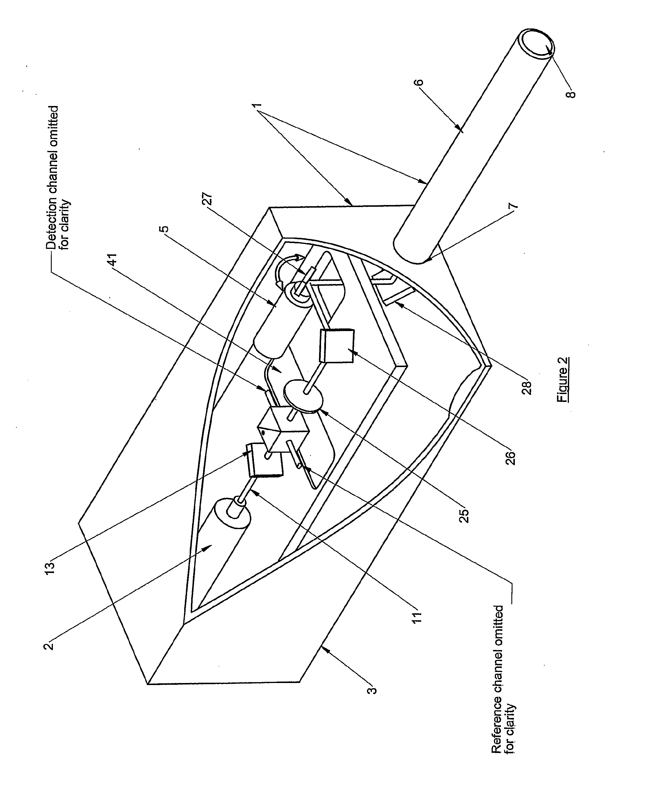
[0056]FIG. 2 shows more detail of the probe 1. The probe 1 comprises a handle 3 containing an multi beam interferometer 41 and scanner 5, and a probe shaft 6. The probe 1 is constructed so that the shaft 6 can be detached from the handle 3...


PUM


Abstract

An optical interference apparatus for carrying out Fourier domain optical coherence tomography including means to provide multiple beams whereby interferograms are recorded simultaneously for a plurality of different focal depths within a substance to be examined, each interferogram being provided by one of the multiple beams. Means are provided for combining images derived from said interferograms for a plurality of different focal depths, whereby a single image may be constructed with an increased depth of field. The axial spacing of the foci is calculated to take into account the Rayleigh range of the focal waist in the substance to be examined.

Description

BACKGROUND OF THE INVENTION[0001]The present invention relates to an interference apparatus and method, particularly an optical coherence tomography apparatus and method and a probe for use therein. We will describe an optical probe and associated methods for use with an imaging technique known as optical coherence tomography (OCT).[0002]In a preferred arrangement, the optical probe may be used in any location which can be reached by a rigid endoscope (or borescope). Potential applications include medical examinations such as colposcopy (cervical cancer screening) and laparoscopy (e.g. in diagnosis and treatment of endometriosis). In another preferred arrangement, the optical probe may be used in more accessible locations which do not require an endoscope. Potential applications include dermatology (e.g. in skin cancer diagnosis).[0003]Internal medical examinations are typically carried out by using an endoscope in which the eye or a CCD camera images the view relayed from the dista...

Claims


Application Information

Patent Timeline
IPC IPC(8): G01N21/00A61B1/04A61B1/07A61B1/303A61B5/00
CPCA61B1/303A61B5/0066A61B2562/0242A61B5/7257A61B5/6852
Inventor SMITH, DAVID STEVENHATTERSLEY, SIMON RICHARDGILKES, ANDREW
Owner MICHELSON DIAGNOSTICS
Learn More