Economical, two component, thermal energy delivery and surface cooling apparatus and its method of use

a cooling apparatus and thermal energy technology, applied in the field of thermal energy delivery devices, can solve the problems of inability to afford devices, inability to economically provide cooling to the endothelial lining of internal ducts, blood vessels, hollows, etc., and achieve the effect of avoiding cross contamination and infection

Inactive Publication Date: 2008-08-14
LOEB MARVIN P
View PDF11 Cites 43 Cited by
  • Summary
  • Abstract
  • Description
  • Claims
  • Application Information

AI Technical Summary

Benefits of technology

[0025]In a preferred embodiment, the balloon is expanded with a cold gas or liquid, which cools the sensitive endothelial lining of, for example, a duct, hollow organ or body cavity prior to and during the emission of laser energy. This cools the endothelial lining of the duct, blood vessel, hollow organ or body cavity and prevents it from being thermally damaged by the laser energy, while allowing the laser energy to penetrate the tissue underlying the endothelial lining to produce its desired effect. The tissue effects of laser energy include shrinkage by photomechanical cross linkage of collagen, protein denaturization, co...

Problems solved by technology

However, fiber-optic based devices are relatively expensive, particularly those which are able to emit laser energy laterally from the axis of the optical fiber at an angle of about 70° to 90°, generally referred to as side-firing laser devices.
Such devices are sold as “single-use,” disposable devices, as they contact body tissue and blood and cannot be safely sterilized and re-used.
However, in the developed countries of Europe, where only about $1,000 to $2,000 is paid for such proc...

Method used


Image

  • Economical, two component, thermal energy delivery and surface cooling apparatus and its method of use
  • Economical, two component, thermal energy delivery and surface cooling apparatus and its method of use
  • Economical, two component, thermal energy delivery and surface cooling apparatus and its method of use

Examples


example

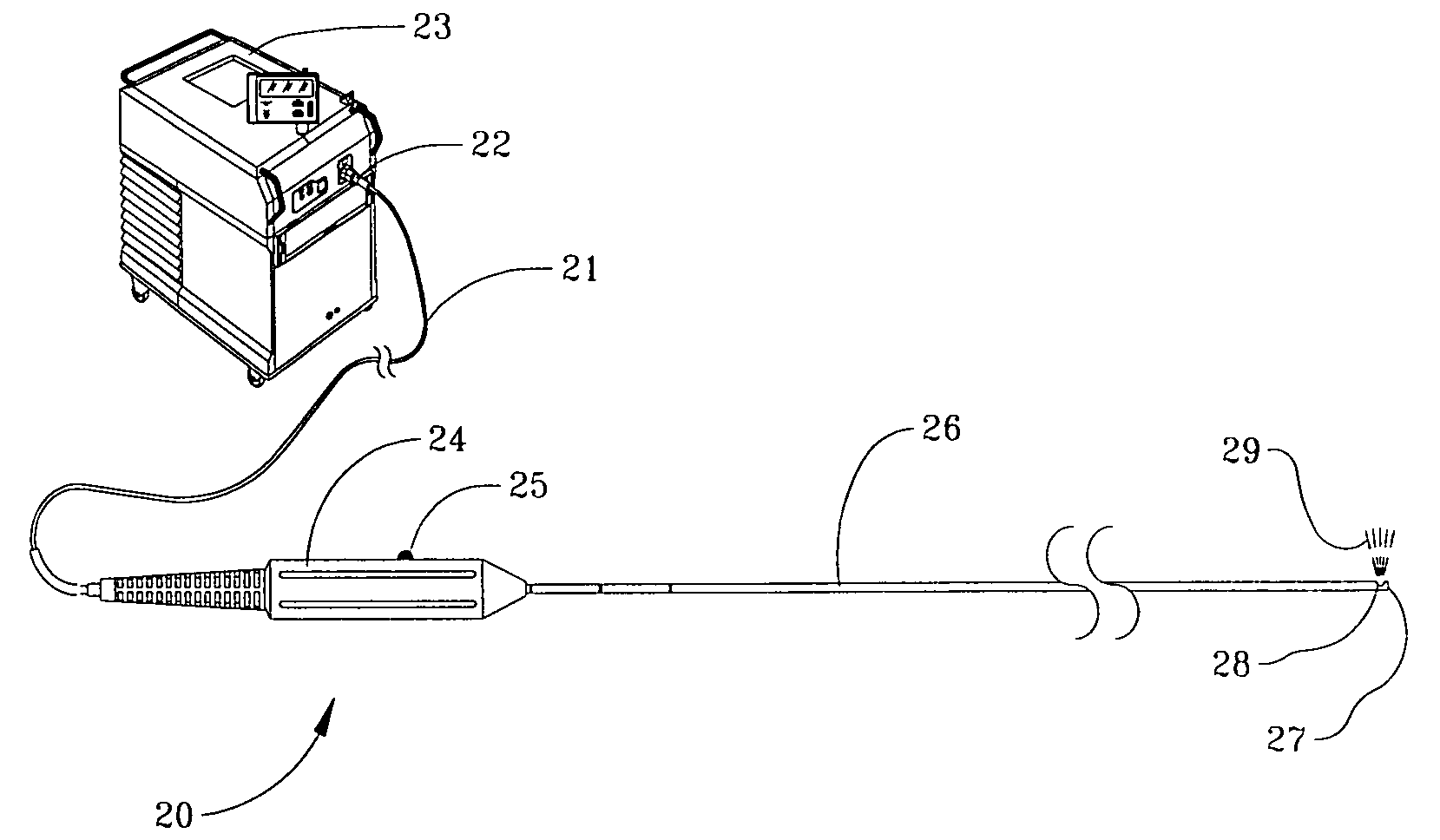
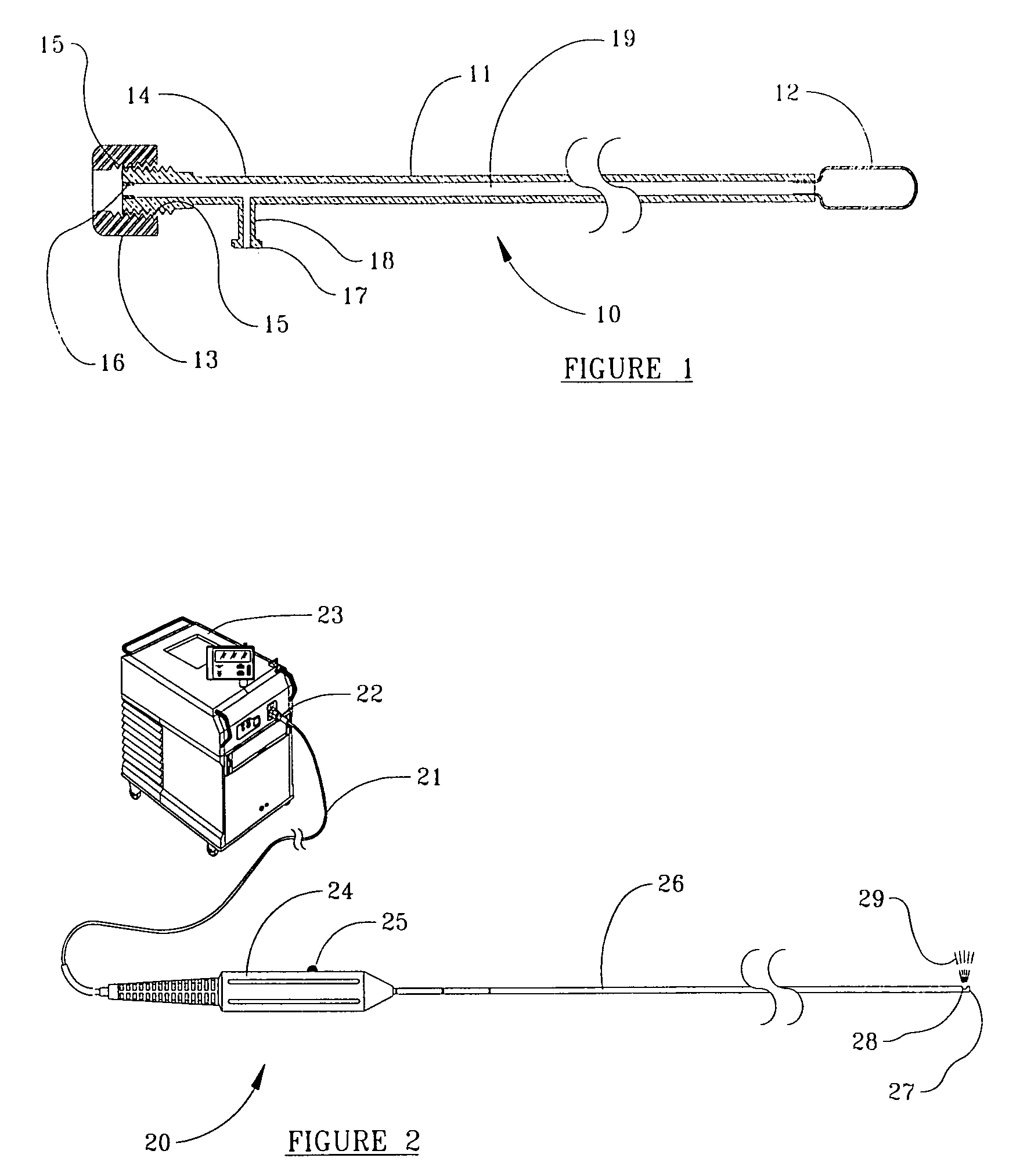
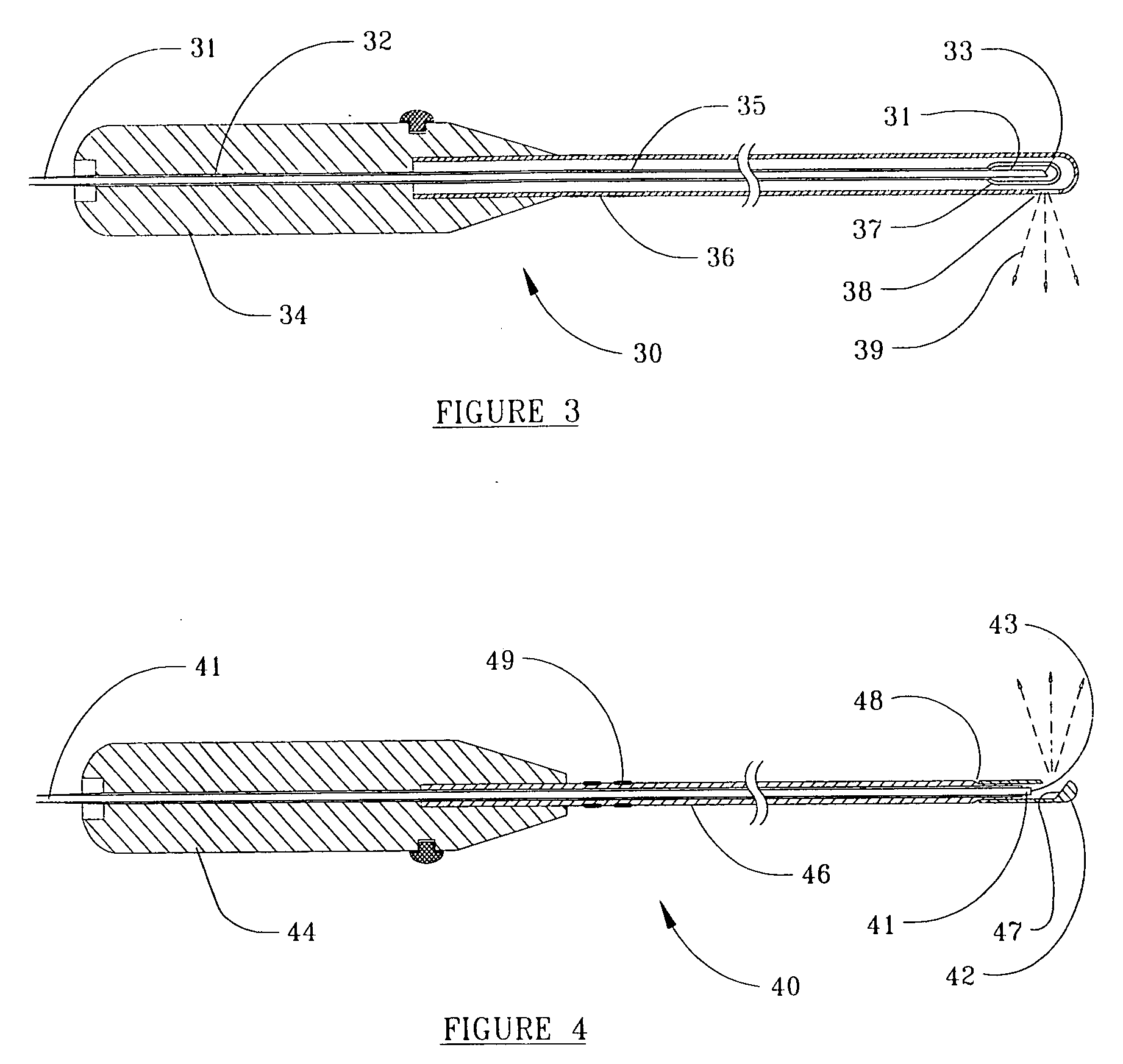
[0081]A group of medical devices were constructed according to embodiments shown in FIGS. 1 and 3. Specifications for selected features are presented below in Table I.

TABLE IDeviceSpecificationLaser Energy Emitting Component:fiber optic365 to 550 micron case diameter3 meters in lengthsheath materialmedical grade stainless steel orPEEKsheath outside diameter1.5 to 2.33 mmemitter configurationBeveled, prism-like optical fibercapillary tubeFused silicapreferred laser typeDiodeCoolant Retainer / Balloon:cannula length10 to 75 cm(handpiece to balloon)cannula outside diameter2 to 3 mmballoon materialsiliconeballoon diameter (inflated)5 to 80 mmport(s)Luer configuration

[0082]The meetings and sizes of the example devices vary by the particular medical application. The example devices provide a reusable higher-cost thermal energy delivery component and a relatively lower cost, disposable coolant component. These devices can be made non-detachable as a single use, disposable device, or detachab...


PUM


Abstract

The present invention is embodied in a medical device which is comprised of a thermal energy delivery component, for example, including an elongate optical fiber terminating in a lateral laser energy emitter, and an outer coolant component, which includes a cannula for receiving the thermal energy delivery component, which terminates in an energy-transmissive balloon for surrounding the thermal energy emitter and providing a tissue-contacting coolant chamber. The cannula portion of the coolant component is moveably sealed around the laser energy delivery component. In one embodiment, a retaining means prevents the thermal energy delivery component from being detached from the coolant component. In an alternate embodiment, there is no retaining means, allowing the more costly thermal energy delivery component to be removed, sterilized and later reused, whereas the less costly outer coolant component, which contacts tissue, blood and body liquids, can be discarded after use.

Description

FIELD OF INVENTION[0001]This invention relates to thermal energy delivery devices which are used to denature, shrink, coagulate, scar, desiccate or vaporize internal body tissues surrounding or underlying a duct, blood vessel, hollow-organ or body cavity, while concomitantly cooling the interior surface of the duct, blood vessel, hollow organ or body cavity to prevent damage to its endothelial lining, in an economical, minimally invasive procedure.BACKGROUND OF THE INVENTION[0002]Thermal energy delivery devices include those emitting coherent light or laser energy, incoherent high intensity white light, incoherent high intensity light of a particular wavelength, microwave and focused ultra-sound energy. Of these, optical fibers for conveying laser energy, sometimes referred to as wave guides, enjoy certain advantages.[0003]Fiber-optic based devices for delivering laser energy have many uses in medicine, as optical fibers are small in diameter, can reach areas of the body difficult t...

Claims


Application Information

Patent Timeline
IPC IPC(8): A61B18/20
CPCA61B18/18A61B2018/1861A61B18/1815
Inventor LOEB, MARVIN P.
Owner LOEB MARVIN P
Why Eureka
Try Eureka