Heating furnace and method for manufacturing honeycomb structure

a technology of heating furnace and honeycomb, which is applied in the direction of manufacturing tools, furnaces, lighting and heating apparatus, etc., can solve the problems of harmful to the environment and the human body, affecting the quality of honeycomb, and raising serious problems

Inactive Publication Date: 2008-08-21
IBIDEN CO LTD
View PDF21 Cites 106 Cited by
  • Summary
  • Abstract
  • Description
  • Claims
  • Application Information

AI Technical Summary

Benefits of technology

[0011]According to an aspect of the present invention, a heating furnace is advantageously provided for calcining an object to be heated. The heating furnace includes a wall defining a furnace space and configured to receive the object in the furnace space, and a heating device configured to raise a temperature within the furnace space. The heating furnace also includes an oxygen supply channel configured to introduce gases containing oxygen into the fu...

Problems solved by technology

Recently, particulates that are contained in exhaust gases discharged from internal combustion engines of vehicles, such as buses and truc...

Method used


Image

  • Heating furnace and method for manufacturing honeycomb structure
  • Heating furnace and method for manufacturing honeycomb structure
  • Heating furnace and method for manufacturing honeycomb structure

Examples


first embodiment

[0090]Hereinafter, a first embodiment of the present invention will be described with reference to drawings.

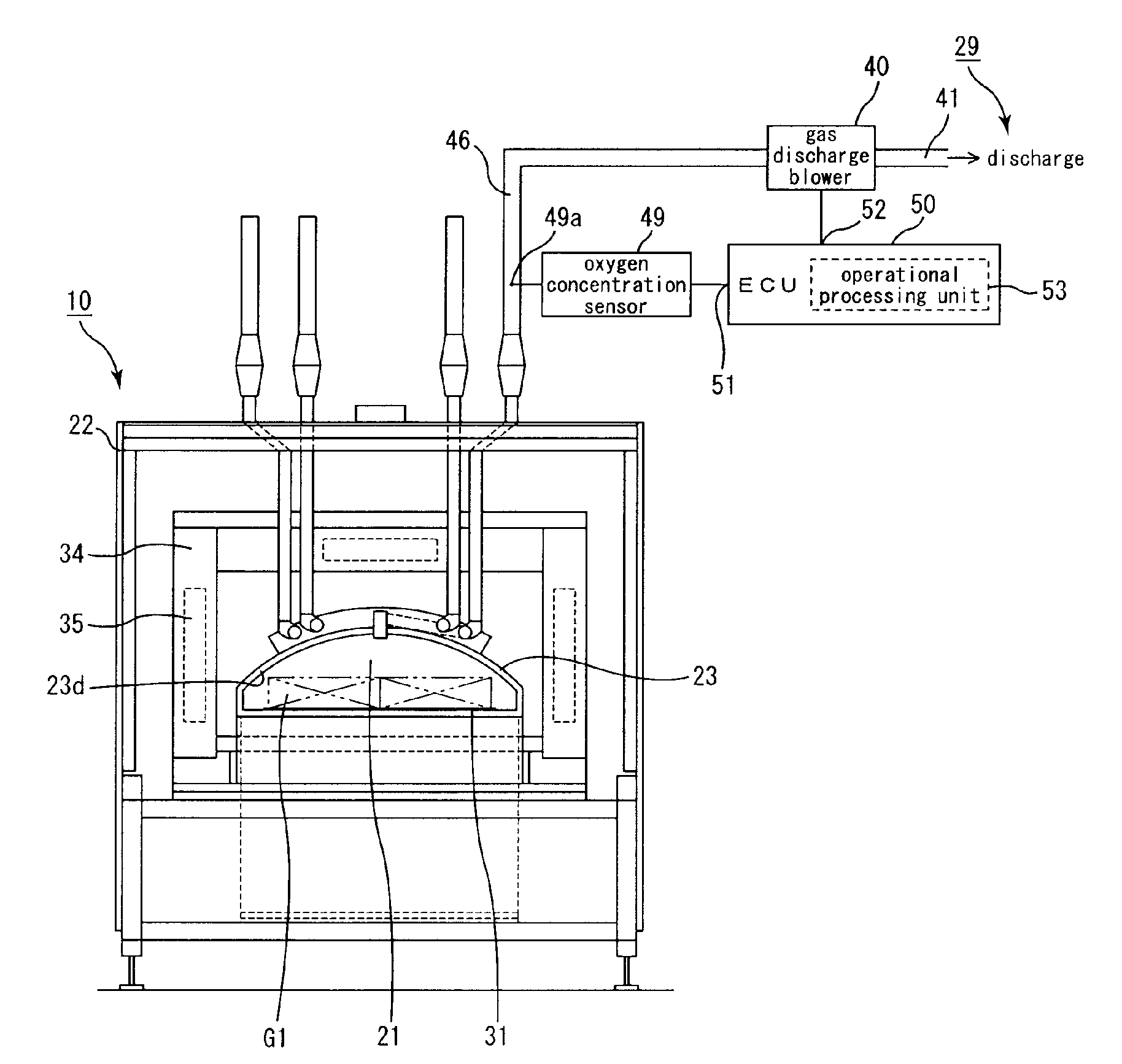
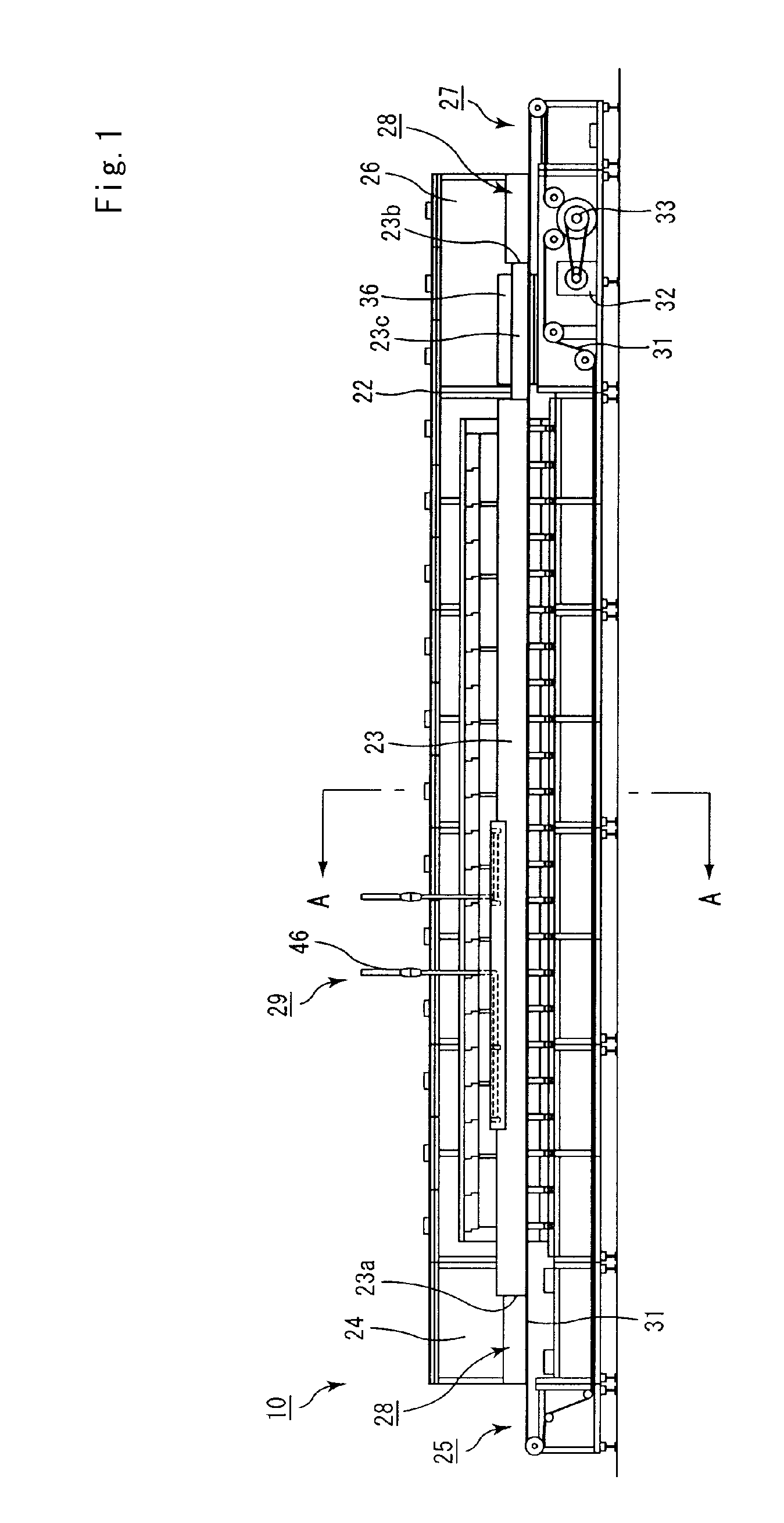
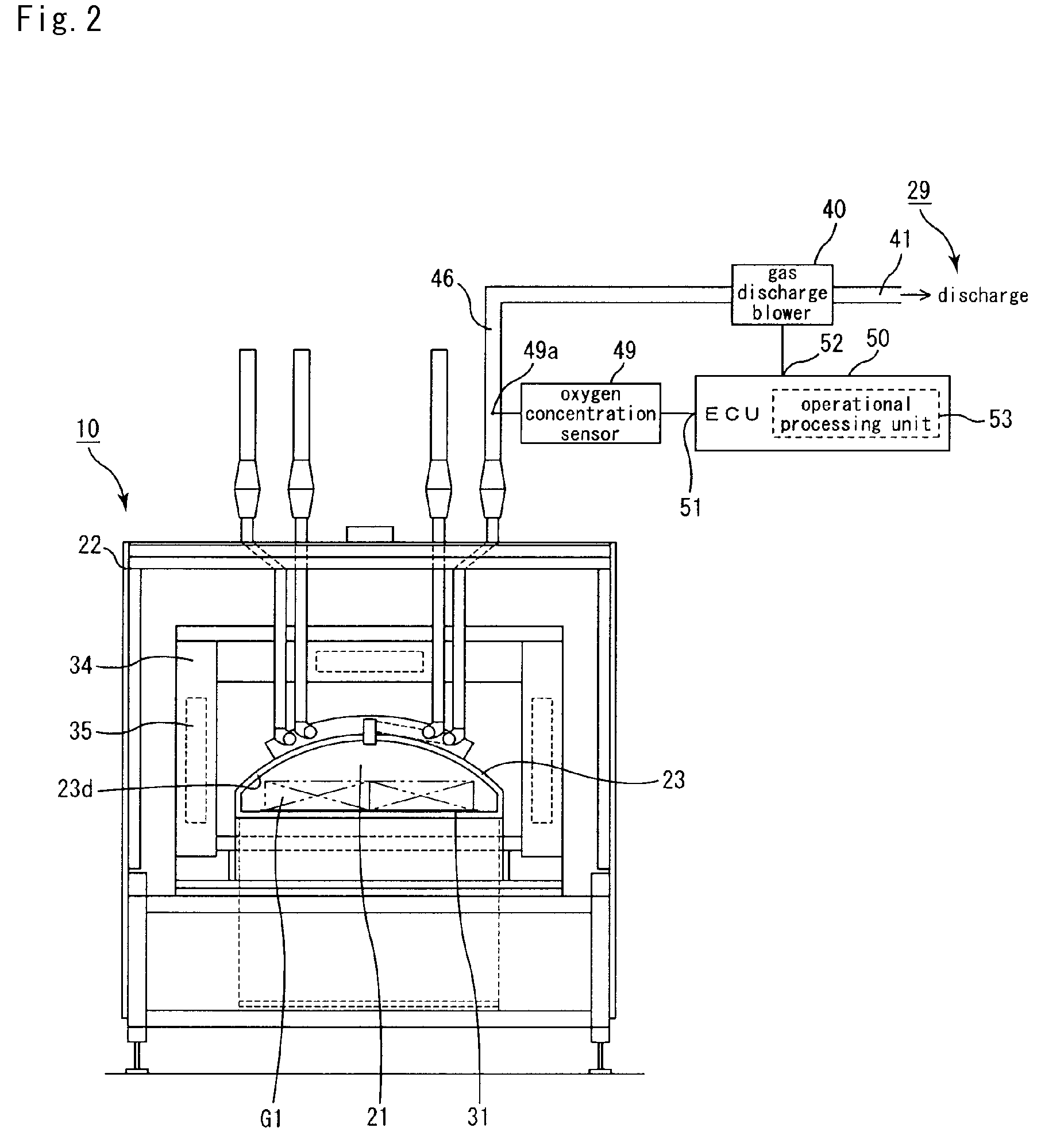
[0091]FIG. 1 is a front view showing a heating furnace 10 of the first embodiment of the present invention. FIG. 2 is a cross-sectional view of the heating furnace taken along line A-A in FIG. 1.

[0092]The heating furnace 10 shown in FIGS. 1 and 2 is provided with four gas discharge channels 46. FIG. 2 shows only devices such as a measurement devices and a gas discharge blower 40 installed in right-end gas discharge channel, while these devices are installed in the respective gas discharge channels 46, and a mechanism installed in other gas discharge channels are omitted.

[0093]The heating furnace 10 shown in FIG. 1 is a continuous furnace. In a transversely long main body frame 22 forming the heating furnace 10, a tubular muffle 23 made of a refractory material is supported transversely in almost all portions except the carrying-in unit 25 and a carrying-out unit 27, and an inl...

example 1

[0158]A powder mixture was prepared by mixing 250 kg of α-type silicon carbide powder with an average particle diameter of 10 μm, 100 kg of α-type silicon carbide powder with an average particle diameter of 0.5 μm, and 20 kg of an organic binder (methyl cellulose).

[0159]Next, separately, a liquid mixture was prepared by mixing 12 kg of a lubricant (UNILUB, manufactured by NOF CORPORATION), 5 kg of a plasticizer (glycerin), and 65 kg of water, and the liquid mixture and the powder mixture were mixed by a wet mixing machine to prepare a wet mixture.

[0160]The water content of the prepared wet mixture was 14% by weight.

[0161]Next, the wet mixture was transported to an extrusion molding apparatus by using a transportation device and put into the raw material inlet of the extrusion molding device.

[0162]The water content of the prepared wet mixture was 13.5% by weight immediately before the putting into the extrusion molding machine.

[0163]Thereafter, a raw molded body with an approximately...

reference example 1

[0178]The degreasing process was carried out in the same manner as Example 1 to manufacture honeycomb fired bodies, except that the program set in the computation processing unit 53 was changed to adjust the flow rate of the gases passing through the gas discharge channels 46 in a range of 5 to 100 m3 / h (Normal), and the gas discharge blower 40 was continuously operated according to this program.


PUM

PropertyMeasurementUnit
Temperatureaaaaaaaaaa
Flow rateaaaaaaaaaa
Volumeaaaaaaaaaa

Abstract

A heating furnace for calcining an object to be heated. The heating furnace includes a wall defining a furnace space and configured to receive the object in the furnace space, and a heating device configured to raise a temperature within the furnace space. The heating furnace also includes an oxygen supply channel configured to introduce gases containing oxygen into the furnace space. The oxygen supply channel is formed as an opening in a part of the wall surrounding the furnace space. The heating furnace further includes a gas discharge channel fluidly connected to the furnace space and configured to discharge gases in the furnace space to an outside of the furnace space, and a measurement device installed in the gas discharge channel and configured to measure properties of the gases passing through the gas discharge channel.

Description

CROSS-REFERENCE TO RELATED APPLICATIONS[0001]The present application claims priority under 35 U.S.C. §119 to PCT Application No. PCT / JP2007 / 053181, filed Feb. 21, 2007, the contents of which are incorporated herein by reference in their entirety.BACKGROUND OF THE INVENTION[0002]1. Field of the Invention[0003]This invention relates to a heating furnace and a method for manufacturing a honeycomb structure.[0004]2. Discussion of the Background[0005]Recently, particulates that are contained in exhaust gases discharged from internal combustion engines of vehicles, such as buses and trucks, and construction machines and the like, have raised serious problems as those particulates are harmful to the environment and the human body. For this reason, there have been proposed various kinds of particulate filters using honeycomb structures made of porous ceramics for capturing the particulates contained in exhaust gases and purifying the exhaust gases. Further, honeycomb structures that allow c...

Claims


Application Information

Patent Timeline
IPC IPC(8): F27D19/00F27D7/00B28B1/00
CPCC04B35/565C04B35/6365C04B35/638C04B2235/5436C04B2235/5445C04B2235/5472F27D21/00C04B2235/6586C04B2235/9623F27B9/30F27B9/40F27D19/00C04B2235/6584
Inventor SAIJO, TAKAMITSUHIGUCHI, KOJI
Owner IBIDEN CO LTD
Why Eureka
Try Eureka