Polymer encapsulation for medical device

a technology of medical devices and polymers, applied in circulatory assistance devices, therapy, heart stimulators, etc., can solve the problems of low fluid permeability, inability to meet the needs of patients, and inability to withstand prolonged use, so as to prevent component leakage

Inactive Publication Date: 2008-08-21
THORATEC CORPORTION
View PDF48 Cites 48 Cited by
  • Summary
  • Abstract
  • Description
  • Claims
  • Application Information

AI Technical Summary

Benefits of technology

[0018]Preferably, the set of electromagnetic stator coils are en...

Problems solved by technology

Also many of these implantable medical devices include components that are potentially toxic, if these components are allowed to corrode, degrade or oxidize, which commonly occurs to iron, copper based alloys and magnet materials used in implanted electrical and mechanical components.
However PEEK has a low level of fluid permeability which may induce corrosion within encapsulated metal components of permanently implanted devices.
According to this disclosed configuration of '475, non-biocompatible or toxic components...

Method used


Image

  • Polymer encapsulation for medical device
  • Polymer encapsulation for medical device
  • Polymer encapsulation for medical device

Examples


first embodiment

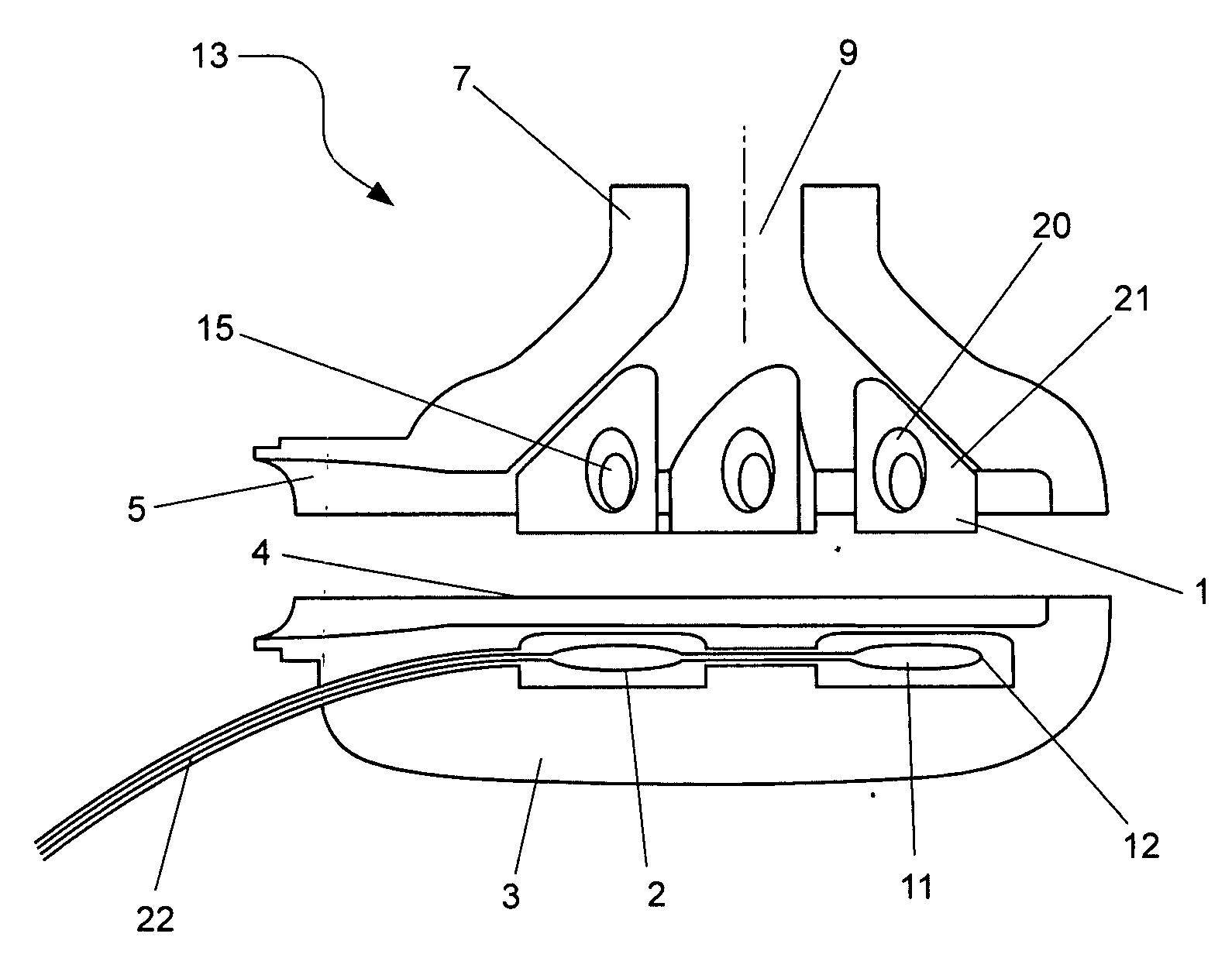
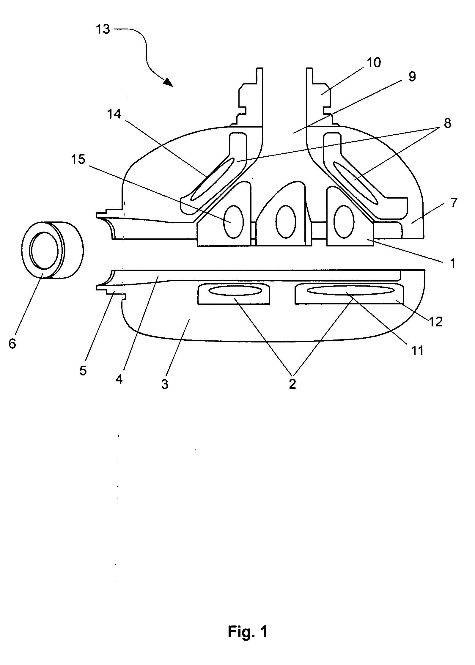
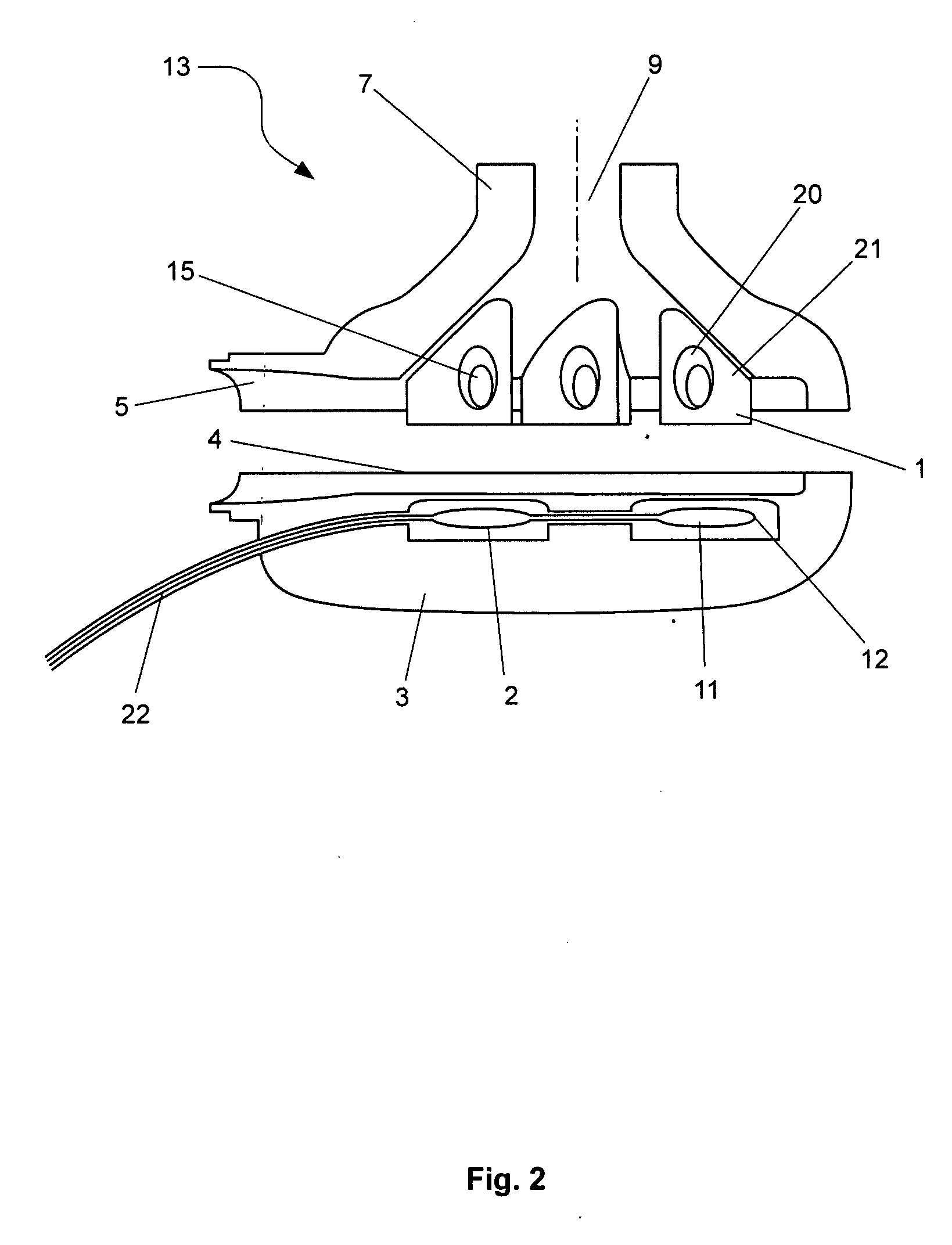
[0035]In this first embodiment, the impeller is preferably constructed from a titanium alloy. The advantage with using a titanium alloy is that it has the mechanical stability, biocompatibility and general dimension stability which are critical for use with hydrodynamic bearings on the outer edges of the impeller 1. The impeller 1 preferably includes four blades mounted in a general circular arrangement and each of the blades has a general shark fin shape, as per FIG. 1. Each blade includes a permanent magnet 15 which interacts with the energised stator coils 2 and 8 in the base and upper housing portions 3 and 7. Typically, the permanent magnets 15 are constructed from neodymium-iron-boron magnets or rare earth magnets. In addition, the use of titanium alloy at approx 500 micron thickness allows for the blade enclosures to maximise the volume of magnet material enclosed, which contributes to motor efficiency.

[0036]A second preferred embodiment of the present invention is depicted i...

third embodiment

[0041]A third embodiment would be to construct the rotor from polymer in a similar manner to the housing. The permanent magnets 15 are encapsulated within each blade of the impeller 1. Since the magnet material is prone to corrosion, an option would be to coat the permanent magnets 15 with parylene prior to encapsulation to provide a thin, highly conformal, pin-hole free moisture-resistant barrier. Forms of parylene are stable at relatively high temperatures (melting point 400° C. and above) and biocompatible. They would thus be stable when exposed to further injection moulding steps. For further moisture protection, the magnet, in the parylene-coated or the non-coated form, is then encapsulated within a layer of the first polymer 20 which is relatively fluid resistant and the first polymer is injection moulded within a second polymer, which may be a poly-ether 21 or PTFE. Additives may be mixed with the second polymer to increase its dimensional stability and to prevent warping or ...


PUM


Abstract

A rotary blood pump comprising an impeller suspended hydrodynamically within pump housing by thrust forces generated by said impeller during movement in use of said impeller as it rotates about an impeller axis, and the driving torque of said impeller is derived from the magnetic interaction between permanent magnets within the blades of said impeller and windings within said housing, and wherein said windings are encapsulated by a first fluid resistant polymer material, and said housing is at least partially made of a second polymer material that encapsulates said first polymer material.

Description

TECHNICAL FIELD [0001]The present invention relates to an improved polymer encapsulation for medical device.BACKGROUND[0002]Many implantable medical devices have been previously constructed from polymeric materials. Also many of these implantable medical devices include components that are potentially toxic, if these components are allowed to corrode, degrade or oxidize, which commonly occurs to iron, copper based alloys and magnet materials used in implanted electrical and mechanical components.[0003]There has been a long felt need for an implantable medical device primarily constructed of polymeric components that also includes corrodible components, such as iron or copper, configured in a manner to prevent corrosion.[0004]One of the most commonly used polymers in the construction of implantable medical devices is polyether ether ketone (‘PEEK’) because of its biocompatibility, excellent chemical resistance and mechanical strength. However PEEK has a low level of fluid permeabilit...

Claims


Application Information

Patent Timeline
IPC IPC(8): A61M1/12A61K9/22A61M60/178A61M60/232A61M60/419A61M60/422A61M60/804A61M60/82A61M60/824
CPCA61M1/101A61M1/122A61M1/1031A61M1/1017A61M60/82A61M60/824A61M60/422A61M60/148A61M60/419A61M60/232A61M60/178A61M60/804
Inventor JAMES, NATALIE
Owner THORATEC CORPORTION
Why Eureka
Try Eureka