Transmission Electron Microscope Provided with Electronic Spectroscope

a technology of electron microscope and electronic spectroscope, which is applied in the direction of optical radiation measurement, instruments, heat measurement, etc., can solve the problems of deterioration of device characteristics and reliability degradation, difficult to compare the shape of energy loss near-edge structure or minimal chemical shift, and difficult to calculate the correct observation magnification of the spectral image. , to achieve the effect of high efficiency, high accuracy and good efficiency

Inactive Publication Date: 2008-08-28
HITACHI HIGH-TECH CORP
View PDF3 Cites 16 Cited by
  • Summary
  • Abstract
  • Description
  • Claims
  • Application Information

AI Technical Summary

Benefits of technology

[0023]As described above, a feature of the present invention is a transmission electron microscope which is provided with an electronic spectroscope, and is capable of acquiring a spectral image formed in two orthogonal axes of an energy dispersion axis and a position information axis. The transmission electron microscope has a correction system which is for correcting the acquired spectral image; and the correction system uses a transmission electron microscope image and the spectral image, and corrects the spectral image by each image pattern in a direction parallel to an energy dispersion axis of each image. According to the electron microscope o...

Problems solved by technology

Processing dimensions of a silicon semiconductor, a magnetic device, and the like have been becoming minute and their high integration has been being achieved; and deterioration of device characteristics and degradation of reliability have been further becoming important problems.
However, in the case of such a technique, the aberration and the position of origin of the electron energy loss spectrum are changed by a drift in accelerating voltage of the electron beam and a change in magnetic field and electric field due to a disturbance change in device periphery; and therefore, it is difficult to compare shapes of the energy loss near-edge structure or minimal chemical shifts, in the electron energy loss spectra for measurement positions.
It is possible to calculate the observation magnification of the ...

Method used


Image

  • Transmission Electron Microscope Provided with Electronic Spectroscope
  • Transmission Electron Microscope Provided with Electronic Spectroscope
  • Transmission Electron Microscope Provided with Electronic Spectroscope

Examples


Embodiment Construction

[0037]Preferred embodiments according to the present invention will be described in detail below with reference to drawings. In addition, the same reference numerals are given in principle to identical members in all the drawings which are for explaining the preferred embodiments, and their repetitive descriptions will be omitted.

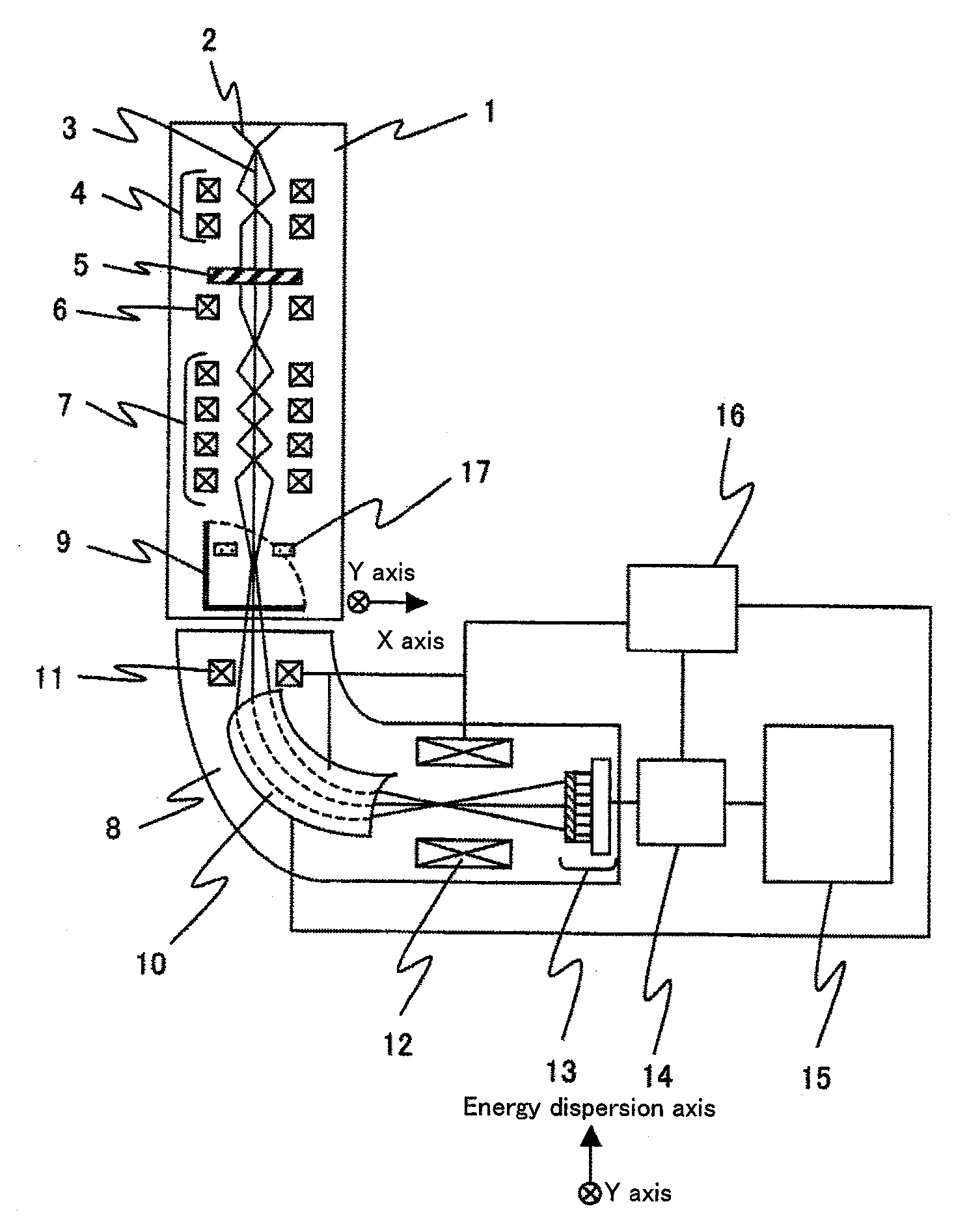
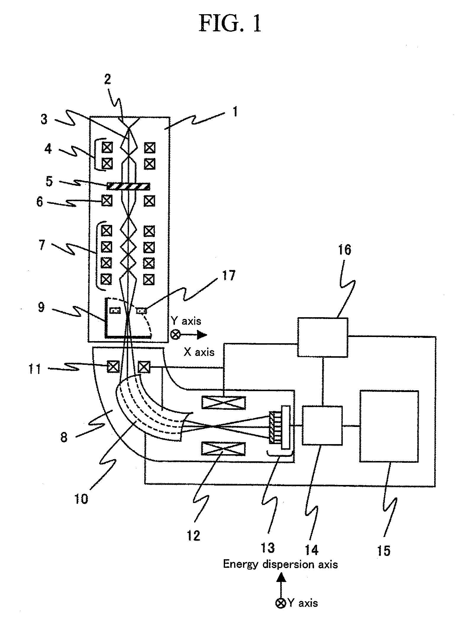
[0038]FIG. 1 is a schematic configuration view showing one example of a transmission electron microscope with an electronic spectroscope that is one preferred embodiment according to the present invention.

[0039]The transmission electron microscope with an electronic spectroscope of the present preferred embodiment is composed of a transmission electron microscope 1, an electronic spectroscope 8, an image display device 14, a central control device 16, a system for correcting magnification and position 15, and the like. The transmission electron microscope 1 includes an electron source 2 which emits an electron beam 3, a convergent lens 4, an objective lens ...


PUM


Abstract

In order to correct measurement magnification and measurement position of a spectral image with high efficiency and with high accuracy using an electronic spectroscope and a transmission electron microscope regarding the spectral image formed in two orthogonal axes which are an amount of energy loss axis and a measurement position information axis; a method for correcting magnification and position and a system for correcting magnification and position, both of which are capable of correcting measurement magnification and measurement position of a spectral image with high efficiency and with high accuracy using an electronic spectroscope and a transmission electron microscope regarding the spectral image formed in two orthogonal axes which are an amount of energy loss axis and a measurement position information axis, are provided.

Description

BACKGROUND OF THE INVENTION[0001]1. Field of the Invention[0002]The present invention relates to a transmission electron microscope provided with an electronic spectroscope which spectrally decomposes an electron beam by an amount of energy which the electron beam has and, more particularly, relates to a transmission electron microscope which makes a convergent position differ in an energy dispersion direction of an electronic spectroscope and a direction perpendicular to the energy dispersion direction. Furthermore, the present invention relates to a method for correcting magnification or position that can perform correction of magnification or correction of measurement position of a spectral image acquired by the transmission electron microscope with high efficiency and high accuracy, and relates to a correction system for achieving the correction method.[0003]2. Description of the Related Art[0004]Processing dimensions of a silicon semiconductor, a magnetic device, and the like h...

Claims


Application Information

Patent Timeline
IPC IPC(8): G01N23/00
CPCH01J37/05H01J37/09H01J37/244H01J37/26H01J37/265H01J2237/2802H01J2237/057H01J2237/24455H01J2237/2446H01J2237/24485H01J2237/0453
Inventor TERADA, SHOHEITANIGUCHI, YOSHIFUMI
Owner HITACHI HIGH-TECH CORP
Why Eureka
Try Eureka