Digital phase estimator, digital phase locked loop and optical coherent receiver

Active Publication Date: 2008-08-28
FUJITSU LTD
View PDF2 Cites 65 Cited by
  • Summary
  • Abstract
  • Description
  • Claims
  • Application Information

AI Technical Summary

Benefits of technology

[0020]The digital phase locked loop according to the present invention compensates the phase difference between the carrier signal and the local oscillator signal by means of the constellation rotator in the digital domain. In comparison with the solutions of the prior art, the present invention has the following notable advantages: the freely oscillating local oscillator laser avoids the difficulties in

Problems solved by technology

The analog phase locked loop is relatively low in speed due to its inherent loop delay.
Moreover, such an analog phase locked loop has the following disadvantages: low control speed due to its long loop delay; high requirements on the phase noise of the carrier and the voltage-controlled oscillator; and larg

Method used


Image

  • Digital phase estimator, digital phase locked loop and optical coherent receiver
  • Digital phase estimator, digital phase locked loop and optical coherent receiver
  • Digital phase estimator, digital phase locked loop and optical coherent receiver

Examples


first embodiment

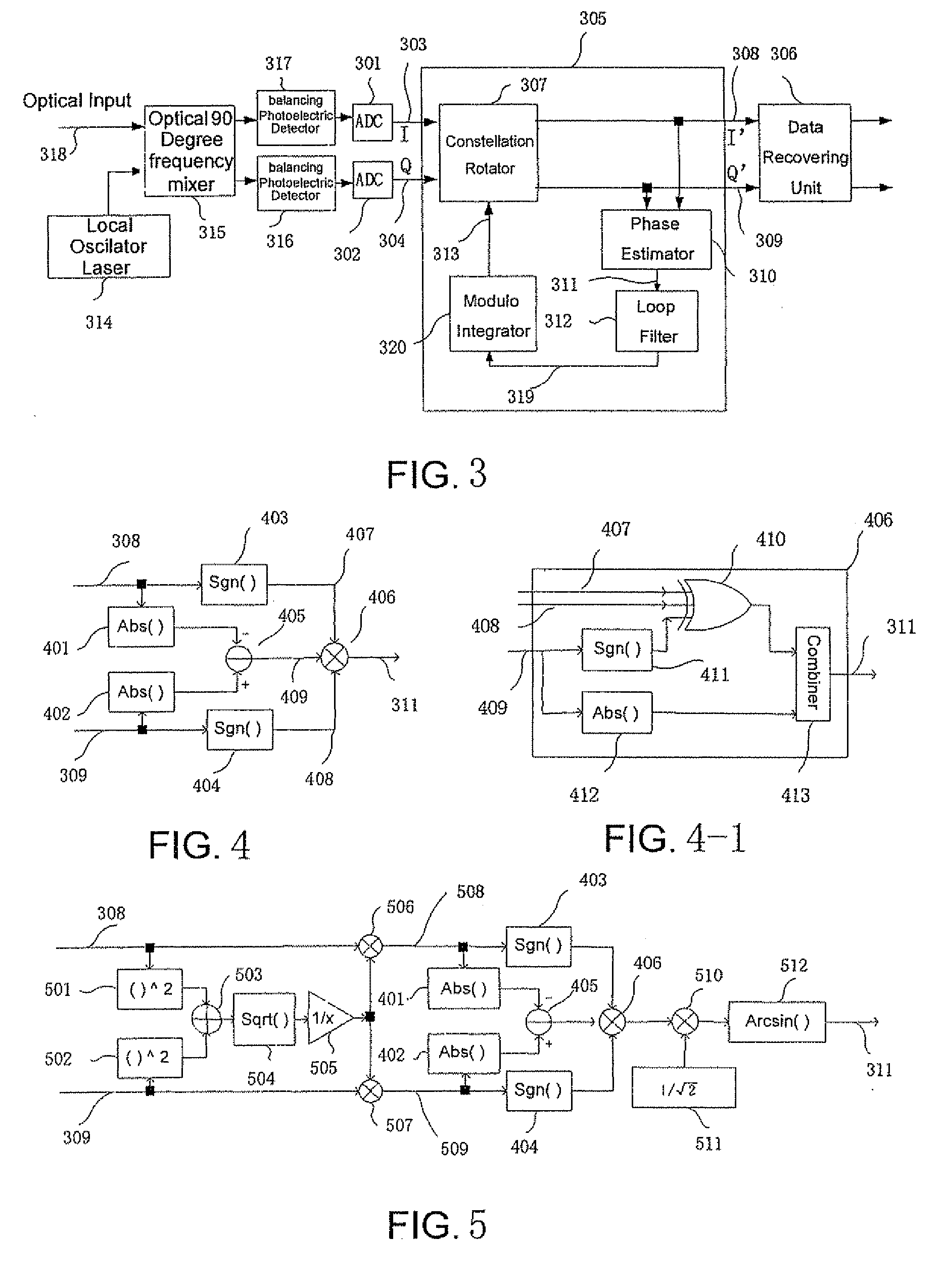
[0036]FIG. 3 shows an overall structure of the optical coherent receiver with a digital phase locked loop according to the present invention.

[0037]As shown in FIG. 3, similar to the prior art optical coherent receiver as shown in FIG. 2, the optical coherent receiver according to the first embodiment of this invention comprises a local oscillator laser 314 for supplying a local oscillator optical signal, an optical 90 degree frequency mixer 315 for mixing a received optical signal with the local oscillator optical signal, first and second balancing photoelectric detectors 316 and 317 for converting the optical signals outputted from the optical 90 degree frequency mixer 315 into baseband electrical signals, first and second A / D converters (ADC) 301 and 302 for respectively receiving output signals of the balancing photoelectric detectors 316 and 317 and respectively converting these output signals into digital signals, a digital phase locked loop 305 for compensating a phase differe...

second embodiment

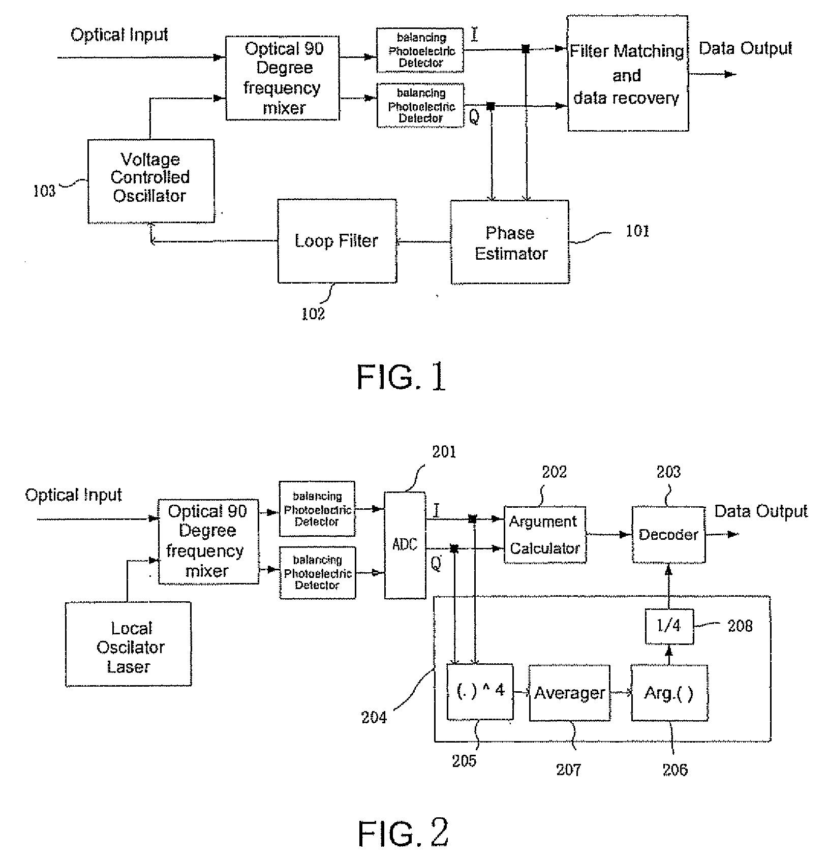
[0075]FIG. 10 shows the structure of an optical coherent receiver based on feed-forward phase estimation according to the present invention using a phase estimator as shown in FIG. 4.

[0076]Except that the phase estimator 204 as shown in FIG. 2 is replaced with a phase estimating section 204′, the optical coherent receiver as shown in FIG. 10 is the same as that shown in FIG. 2 in terms of the basic structure. The phase estimating section 204′ comprises the phase estimator 310 as shown in FIG. 4 for generating the phase estimation signal 311 in accordance with the inputted signal I+jQ, first and second absolute value calculators 1004 and 1004 for respectively calculating the absolute values of the inputs I and Q, an adder 1006 for calculating a summation 1007 of the absolute values of the inputs I and Q, a look up table 1001 for generating a phase difference 1003 in accordance with the phase estimation signal 311 and the summation of the absolute values of the inputs I and Q, and an ...

third embodiment

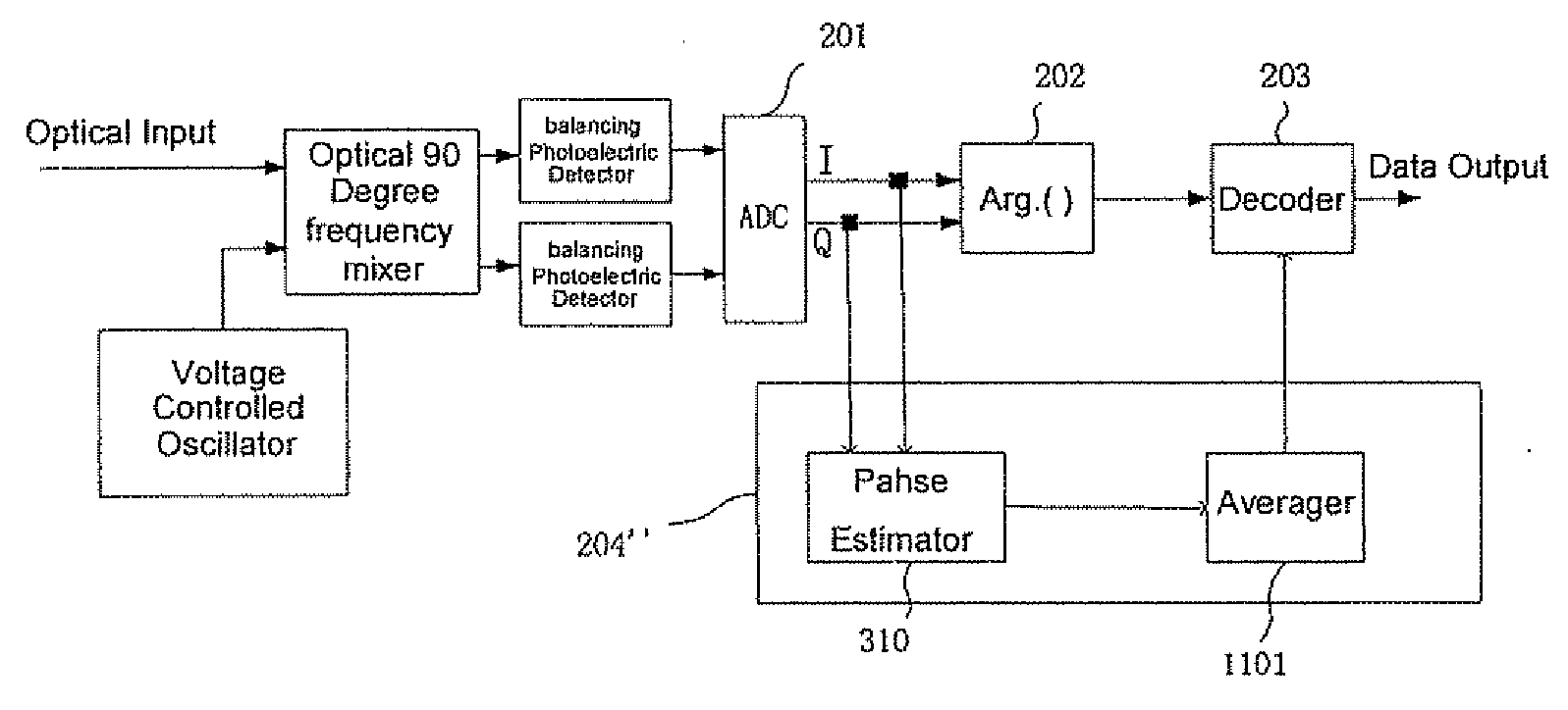
[0084]FIG. 11 shows the structure of an optical coherent receiver based on feed-forward phase estimation according to the present invention using a phase estimator as shown in FIG. 5.

[0085]Except that the phase estimator 204 as shown in FIG. 2 is replaced with a phase estimating section 204″, the optical coherent receiver as shown in FIG. 11 is the same as that shown in FIG. 2 in terms of the basic structure. The phase estimating section 204″ comprises the phase estimator 310 as shown in FIG. 5 for generating a phase difference in accordance with the inputted signal I+jQ, and an averager 1101 for removing the phase difference of noise. First and second input terminals of the phase estimator 310 are respectively connected to first and second output terminals of the analog to digital converter 210, an output terminal of the phase estimator 310 is connected to an input terminal of the averager 1101′ and an output terminal of the averager 1101 is connected to a second input terminal of ...


PUM


Abstract

The present invention provides a digital phase estimator, a digital phase locked loop and an optical coherent receiver. The optical coherent receiver comprises a local oscillator laser, for supplying a local oscillator optical signal; an optical 90 degree frequency mixer, for mixing a received optical signal with the local oscillator optical signal; first and second balancing photoelectric detectors, for converting the optical signals outputted from the optical 90 degree frequency mixer into baseband electrical signals; first and second A/D converters, for respectively converting output signals from the first and the second balancing photoelectric detectors into digital signals; a digital phase locked loop, for compensating a phase difference between a carrier signal of the received optical signal and the local oscillator optical signal, and outputting the compensated signal; and a data recovering unit, for recovering data from the compensated signal.

Description

[0001]This application claims the priority benefit of Chinese Patent Application No. 200710078758.7, filed Feb. 26, 2007 in the Chinese Patent Office, the disclosure of which is herein incorporated in its entirety by reference.TECHNICAL FIELD[0002]The present invention relates in general to optical communication systems, and in particular to a digital phase estimator and a digital phase locked loop suitable for application in various modulation techniques, as well as an optical coherent receiver using the digital phase estimator or the digital phase locked loop.BACKGROUND[0003]With the increasing requirements on the capacity and flexibility of optical communication systems, the coherent optical communication technology has become increasingly important. In comparison with incoherent technology such as on-off key (OOK) or self-coherent technology such as differential quadrature phase shift key (DQPSK), the coherent technology has the following advantages: it has 3 dB optical signal t...

Claims


Application Information

Patent Timeline
IPC IPC(8): H04B10/06G06E1/04G06F17/10H04B10/07H04B10/516H04B10/556H04B10/58H04B10/61H04L7/00H04L27/22
CPCH04B10/61H04B10/6165H04B10/613H04B10/611H04B10/65
Inventor TAO, ZHENNINGLI, LEIRASMUSSEN, JENS C.
Owner FUJITSU LTD
Why Eureka
Try Eureka