
Method of operating a syngas generator

Inactive Publication Date: 2008-09-04
WESTPORT POWER
View PDF31 Cites 26 Cited by
  • Summary
  • Abstract
  • Description
  • Claims
  • Application Information

AI Technical Summary

Benefits of technology

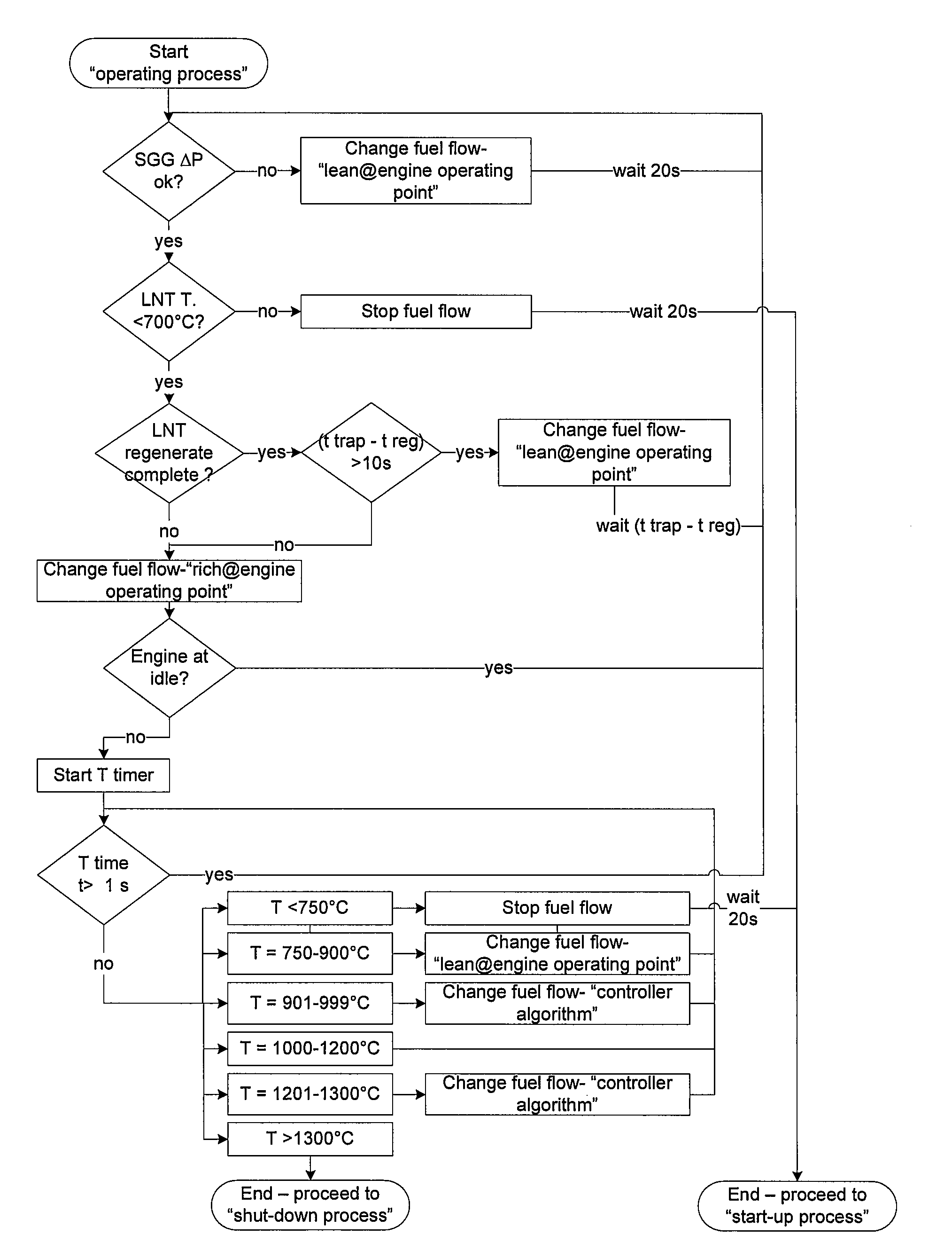
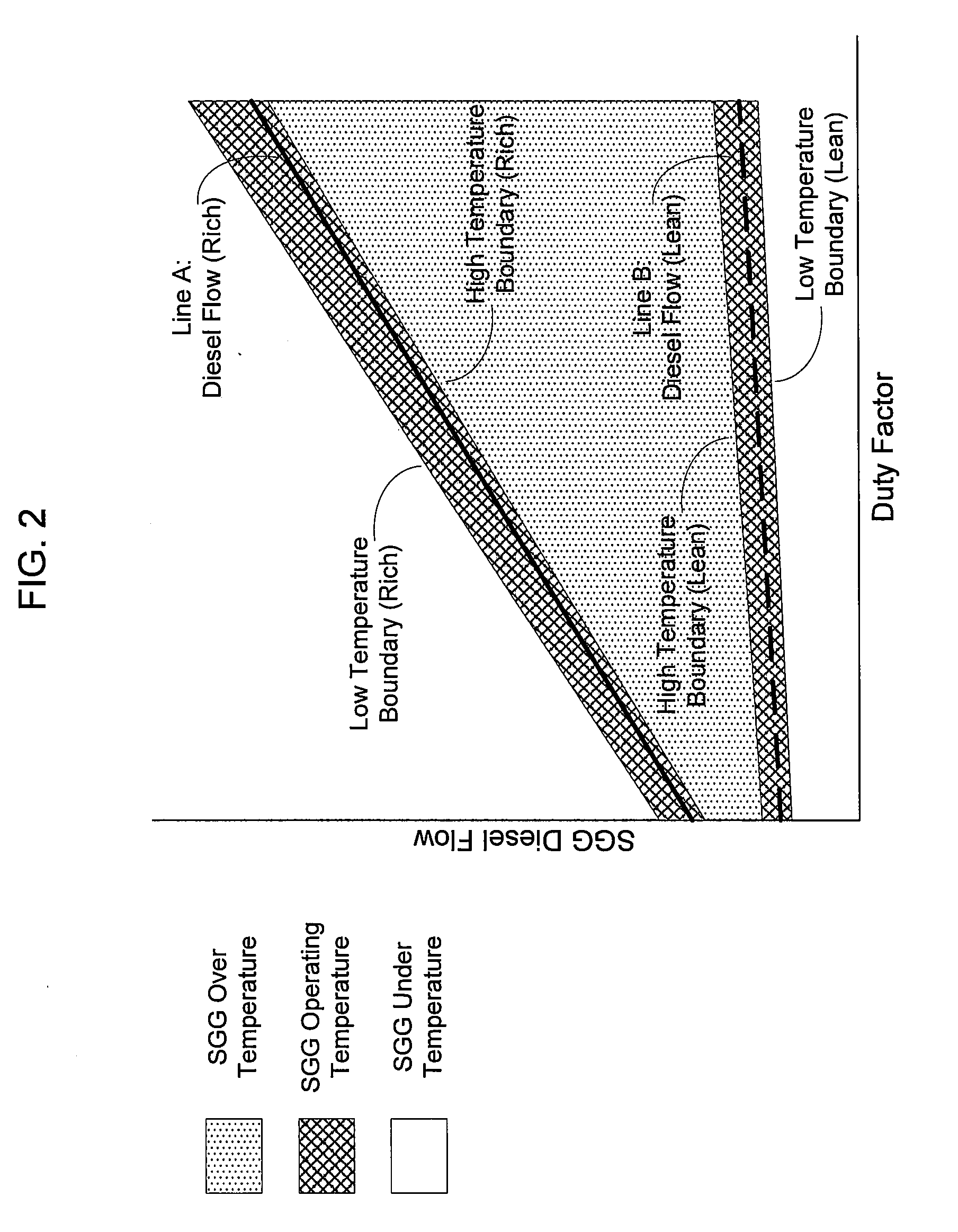
[0032]In embodiments of an apparatus, a syngas generator has an associated control system that is configured to maintain the operating temperature of the syngas generator within a temperature range by switching between a rich mode and a lean mode of operation. The control system can be configured to switch the syngas generator from the lean mode to the rich mode of operation by decreasing the O/C ratio of reactants supplied to the syngas generator. This can be accomplished by adjusting the flow rate of one or both of the reactant streams supplied to the syngas generator in order to switch operation of the syngas generator between the rich and lean modes. The control system is configured to switch the syngas generator from the rich mode t...

Problems solved by technology

However in this situation, the reactant supply and composition will vary over the operating duty cycle of the engine, and this can present some challenges as described below.
Furthermore, the pressure of the engine exhaust stream is generally limited.
Reforming of hydrocarbon fuel, especially heavy hydrocarbons (such as diesel), can be difficult due to the range of components that make up the fuel.
Inadequate vaporization and mixing of the fuel with the engine exhaust stream can lead to localized fuel-rich conditions, resulting in the formation of carbon within the syngas generator.
As mentioned above, the use of the engine exhaust stream as a reactant in the syngas generator imposes inherent supply and operational challenges.
Operating with low and varying concentrations of oxygen, water, carbon dioxide and heat, at the same time as endeavoring to maintain appropriate oxygen-to-carbon (O / C) and steam-to-carbon (S / C) ratios to prevent detrimental carbon build-up over the operating duty cycle of the engine, is a challenge.
While many have attempted to eliminate or minimize carbon formation, practically there is an inevitable tendency for carbon to form during the conversion process of the fuel into syngas.
Over time, carbon accumulation can impede the flow of gases, increase the pressure drop across the syngas generator, and reduce the durability of the syngas generator.
Large accumulations of carbon also have the potential to create excessive amounts of heat that can damage the syngas generator if the carbon is oxidized in a short period of time.
The carbon can also travel downstream of the syngas generator, increasing the back pressure of the engine exhaust and adversely affecting exhaust after-treatment devices, for example, by blocking catalyst and adsorbent reactive sites.
At these elevated temperatures, high thermal stresses can be created during the thermal cycling of the syngas generator.
Thermal stresses can reduce the durability of the syngas generator over its lifetime.
This can reduce the fuel conversion efficiency.(2) Fatiguing of catalyst support materials during large thermal cycles.
Small magnitude thermal cycles are desired, for example, less than a 100° C. range, to promote material durability.(3) High capital cost resulting from the high cost of the catalyst material.(4) Low durability as the catalyst is susceptible to poisoning by contaminants contained in the reactants.
It is not practical to repeatedly start up and shut down the syngas generator.
This would result in the thermal cycling of the syngas generator, which can reduce the durability and reliability of the device, as well as causing delays in the production of syngas.
Furthermore, dynamically responsive start up and shut down of the syngas generator generally requires a fairly complex control system which can increase the cost of the system.
Discarding excess syngas results in a significant fuel penalty that will typically cause the overall efficiency of the engine system to be unacceptably low, and the operating cost to be high.
However, this approach can alter the combustion characteristics of the engine, requiring extensive testing prior to approval for use and warranty by the engine manufacturers.(2) Reducing the supply of reactants (for example, fuel and engine exhaust) to the syngas generator so that it remains sufficiently warm that it can restart within a few seconds, but in the meantime produces smaller quantities of syngas.
This approach increases the complexity of the reactant control which increases the cost of the exhaust after-treatment system.(3) Using a “mini” syngas generator (such as a catalytic partial oxidizer) to feed the main syngas generator sufficiently to keep it warm, so it can be rapidly restarted.
However, this requires a second fuel processor device in the system which adds to the system complexity and cost.
The shortcoming of a catalytic type fuel processor and the above approach to maintain the desired operating temperature of the fuel processor can include:(1) High frequency cycling of the fuel supply is required, for example, less than or equal to 10 seconds to prevent the temperature of the catalyst from moving outside a desired range and to reduce the magnitude of the thermal cycles of the catalyst.(2) Higher operating fuel penalty.(3) Increased component and control complexity and cost.

Method used


Image

  • Method of operating a syngas generator
  • Method of operating a syngas generator
  • Method of operating a syngas generator

Examples


Embodiment Construction

)

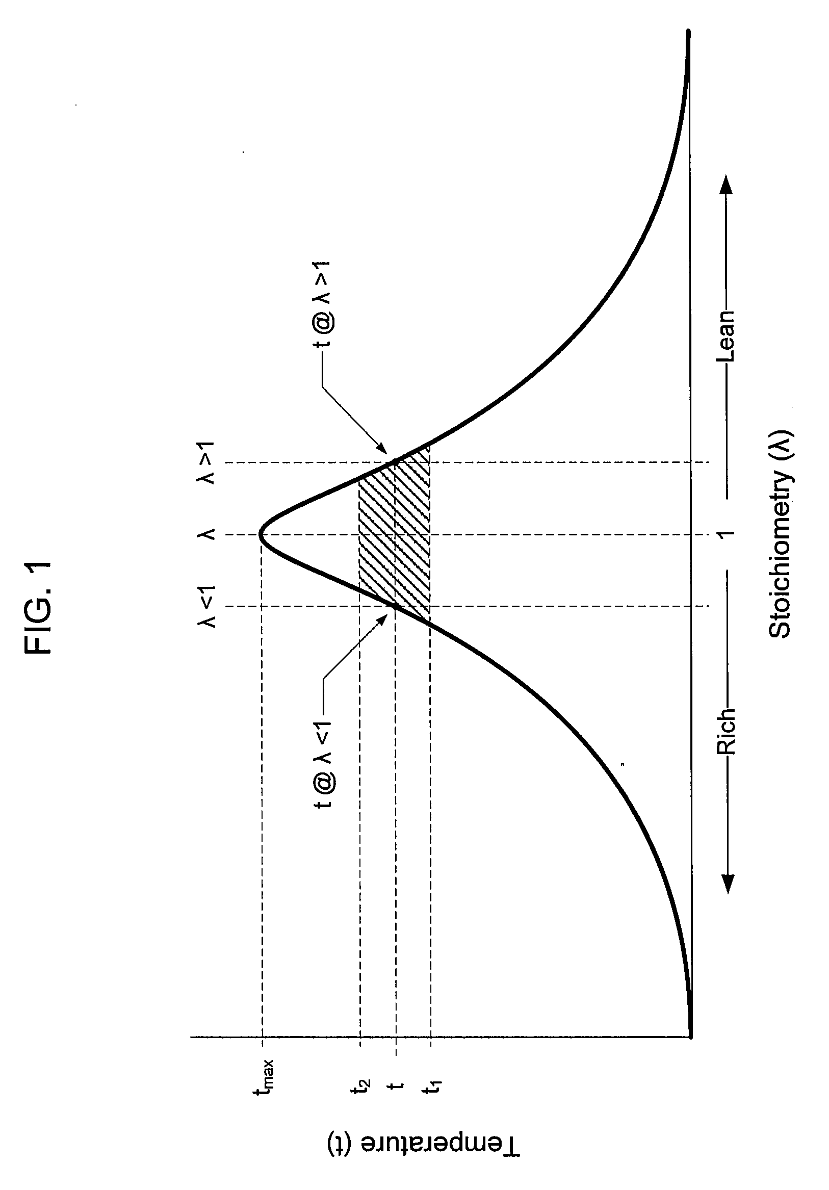
[0040]In preferred embodiments of the present method and apparatus for operating and controlling a syngas generator, during the normal operating process the syngas generator is operated within and switched between at least two modes of operation, namely a lean mode and a rich mode. The syngas generator is operated and maintained within a desired reaction temperature range in both modes. Generally, the syngas generator temperature refers to the reaction temperature within the syngas generator. The operating mode can be selected, for example, depending on the syngas output requirement, and / or the need for carbon removal in the syngas generator and / or other factors.

[0041]FIG. 1 is a simplified graphical illustration showing the change in operating temperature of a syngas generator as the ratio of oxidant and fuel supplied to the syngas generator (or the oxygen-carbon ratio) is varied. The curve is not necessarily to scale, nor necessarily symmetrical or of the profile shown. When the ...


PUM


Abstract

A method of operating a syngas generator within a desired temperature range, despite a need for intermittent syngas output, involves switching between operating the syngas generator in a rich mode and a lean mode. Operation of the syngas generator in both the rich mode and the lean mode sustains the operating temperature of the syngas generator within that desired temperature range, particularly for non-catalytic reactors. The method of switching from the lean mode to the rich mode of operation can include decreasing the oxygen-to-carbon ratio of reactants supplied to the syngas generator. The flow rate of one or more of the reactant streams supplied to the syngas generator can be actively controlled in order to switch operation of the syngas generator between the rich and lean modes.

Description

CROSS-REFERENCE TO RELATED APPLICATION(S)[0001]This application is related to and claims priority benefits from U.S. Provisional Patent Application Ser. No. 60 / 890,600, entitled “Method of Operating a Syngas Generator”, filed on Feb. 19, 2007, which is hereby incorporated by reference in its entirety.FIELD OF THE INVENTION[0002]The present invention relates to a method of operating a syngas generator. The method is especially useful in applications where the need for syngas is intermittent or fluctuating, and where the syngas generator is non-catalytic. The method relates particularly to the operation of a syngas generator in an internal combustion engine emissions reduction exhaust after-treatment system, where the engine can be part of a vehicular or non-vehicular system. There can be other uses for the syngas stream within the overall system.BACKGROUND OF THE INVENTION[0003]A syngas generator is a device than can convert a fuel into a gas stream containing hydrogen (H2) and carbo...

Claims


Application Information

Patent Timeline
IPC IPC(8): F01N3/10
CPCC01B3/36C01B2203/0211C01B2203/0255F01N3/0871F01N3/2073F02M25/12F02B1/12F02B3/06F02D41/0235F02D41/027F01N2240/30F01N3/0842F01N3/0253F01N3/206
Inventor JOHANNES, ERIK PAULLI, XUANTIANSEDERQUIST, RICHARD ALLAN
Owner WESTPORT POWER
Learn More