Analysis apparatus and analysis method
a technology of analysis apparatus and analysis method, which is applied in the field of analysis apparatus, can solve the problems of low detection/generation efficiency of terahertz wave, incomplete restoration of transmitted signal, etc., and achieve the effects of less influence on the frequency characteristics of the detection unit, more reliable signal detection and analysis, and improved low efficiency of generation/detection of terahertz wav
- Summary
- Abstract
- Description
- Claims
- Application Information
AI Technical Summary
Benefits of technology
Problems solved by technology
Method used
Image
Examples
example 1
[0067]This Example describes specifically the apparatus and method of the analysis described above. Incidentally, the same descriptions as that mentioned above are omitted.
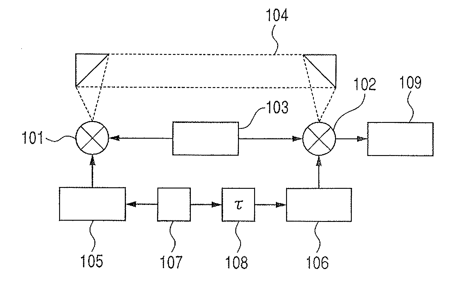
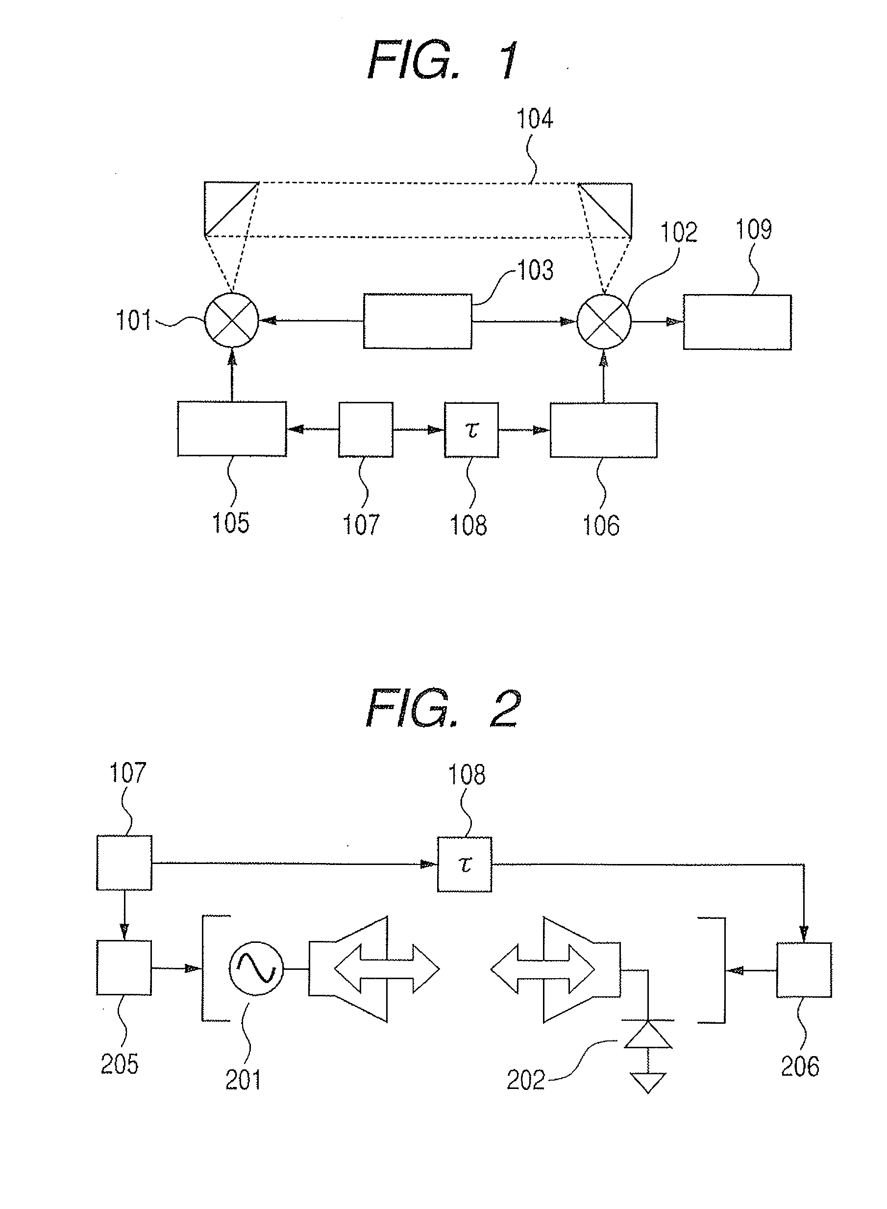
[0068]FIG. 2 illustrates schematically a constitution of the analysis apparatus of this Example. As illustrated in FIG. 2, vibrating unit 205 is employed as band-diffusing unit 105; vibrating unit 206 is employed as band-restoring unit 106; oscillator 201 for emitting a terahertz wave of a simple frequency component is employed as generating unit 101; and detector 202 having sufficient sensitivity for detection of the terahertz wave from oscillator 201 is employed as detecting unit 102.
[0069]A frequency multiplier which utilizes nonlinearity of a semiconductor element is employed as oscillator 201 which emits a simple-frequency terahertz wave. However, the oscillator is not limited thereto. The oscillator includes semiconductor elements like a quantum cascade laser and a resonance tunnel diode; oscillators utilizi...
example 2
[0080]This Example describes another embodiment of the analysis apparatus of the present invention, specifically a modification of Example 1 regarding the band diffusion and band restoration of the terahertz wave. In the description below, the matters common to the above description are omitted.
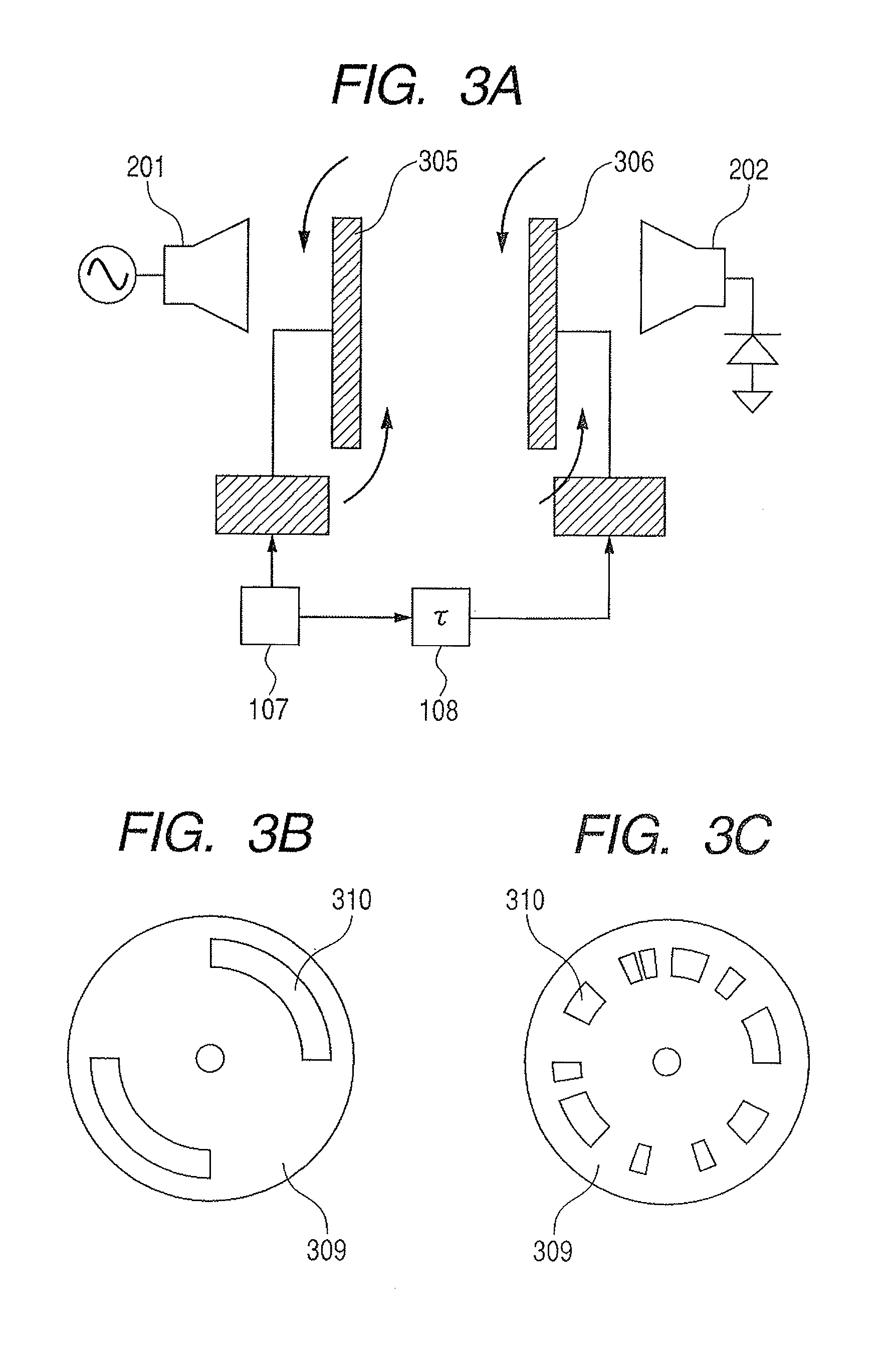
[0081]FIGS. 3A, 3B, and 3C illustrate schematically a constitution of the apparatus and method of the analysis of this Example. FIG. 3A illustrates the entire constitution; and FIGS. 3B and 3C illustrate respectively the constitution of the band diffusion portion and the band restoration portion. In this Example, phase controller 305 is employed as band diffusing unit 105, and phase controller 306 is employed as band restoring unit 106. This Example is different from Example 1 in that band-diffusing unit 105 and band-restoring unit 106 are placed respectively outside oscillator 201 and detector 202.
[0082]Phase controller 305 and phase controller 306 have respectively a rotating disk 309 havin...
example 3
[0090]This Example describes still another embodiment of the analysis apparatus of the present invention, specifically a modification of Example 1 regarding the band of the employed terahertz wave. In the description below, the matters common to the above description are omitted also.
[0091]FIG. 4 illustrates schematically a constitution of the apparatus and method of the analysis of this Example. In this Example, generating element 401 is employed as generating unit 101; detecting element 402 is employed as detecting unit 102; and a pulsed terahertz wave is employed differently from the above Examples in which the terahertz wave is a continuous wave.
[0092]In this Example, generating element 401 and detecting element 402 have respectively an antenna structure formed on a semiconductor substrate. The semiconductor substrate is a GaAs substrate of 100 μm thick having on the surface an LT-GaAs epitaxial growth layer of 1.5 μm thick. The antenna structure is a dipole antenna structure ha...
PUM
| Property | Measurement | Unit |
|---|---|---|
| thick | aaaaa | aaaaa |
| thick | aaaaa | aaaaa |
| length | aaaaa | aaaaa |
Abstract
Description
Claims
Application Information
 - R&D
- Intellectual Property
- Life Sciences
- Materials
- Tech Scout
- Unparalleled Data Quality
- Higher Quality Content
- 60% Fewer Hallucinations
Browse by: Latest US Patents, China's latest patents, Technical Efficacy Thesaurus, Application Domain, Technology Topic, Popular Technical Reports.
© 2025 PatSnap. All rights reserved.Legal|Privacy policy|Modern Slavery Act Transparency Statement|Sitemap|About US| Contact US: help@patsnap.com


