Negative electrode for lithium ion secondary battery and lithium ion secondary battery

a lithium ion secondary battery and negative electrode technology, applied in the direction of secondary cell details, cell components, cell component details, etc., can solve the problems of shortening the charge/discharge cycle life, deformation of the negative electrode current collector, and increasing the size of the negative electrode, so as to improve the coulombic efficiency. , the effect of high lithium-ion conductivity

Inactive Publication Date: 2008-09-04
PANASONIC CORP
View PDF5 Cites 51 Cited by
  • Summary
  • Abstract
  • Description
  • Claims
  • Application Information

AI Technical Summary

Benefits of technology

[0069]Examples of additives include materials that improve coulombic efficiency and materials that deactivate a battery. For example, a material that improves coulombic efficiency decomposes on the negative electrode to form a coating film of high lithium-ion conductivity, thereby enhancing coulombic efficiency. Specific examples of such materials include vinylene carbonate (VC), 4-methyl vinylene carbonate, 4,5-dimethyl vinylene carbonate, 4-ethyl vinylene carbonate, 4,5-diethyl vinyl...

Problems solved by technology

However, when such a material absorbs and desorbs lithium, it expands and contracts due to a change in crystal structure.
As more parts of the negative electrode active material layer become separated from the negative electrode current collector, it becomes more difficult to collect current therefrom, so that the charge/discharge cycle life becomes shorter.
Such stress often causes the ends of the columnar structures adjacent to the slits to separate from the negative electrode current collector.
It is thus impossible to avoid partial separ...

Method used


Image

  • Negative electrode for lithium ion secondary battery and lithium ion secondary battery
  • Negative electrode for lithium ion secondary battery and lithium ion secondary battery
  • Negative electrode for lithium ion secondary battery and lithium ion secondary battery

Examples


example 2

[0104]This example is the same as Example 1 except that protrusion-forming rolls were produced as follows. First, a ceramic layer of chromium oxide was formed on the surface of an iron roll in the same manner as in Example 1. Using a laser, circular first holes (depressions) with a diameter of 12 μm and a depth of 3 μm were made in the surface of the ceramic layer. The first holes were arranged in the close-packed arrangement at an axis-to-axis distance of adjacent holes of 20 μm. Also, the bottom of each first hole had the same shape as the bottom of the first hole in Example 1, and the length from the surface of the ceramic layer to the center of the bottom of the first hole was 3 μm. Next, circular second holes (depressions) with a diameter of 8 μm and a depth of 3 μm were made in the bottom of the first holes so that their axes were aligned with the axes of the first holes. The second holes also had the same shape as the first holes, and the length from the surface of the cerami...

example 3

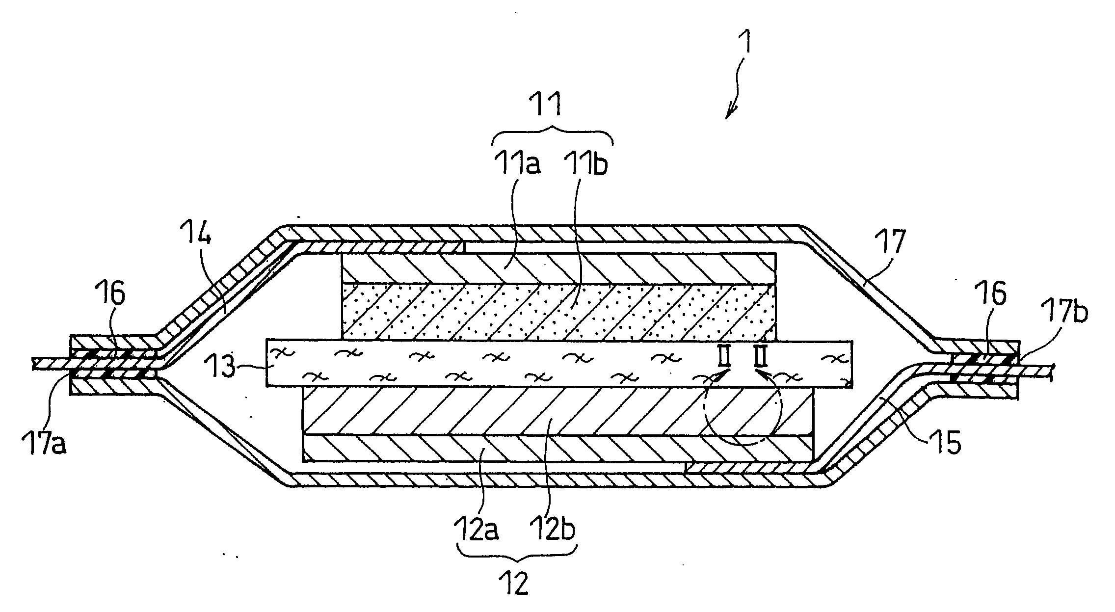
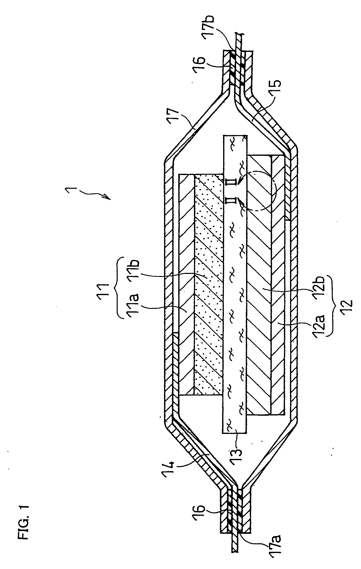
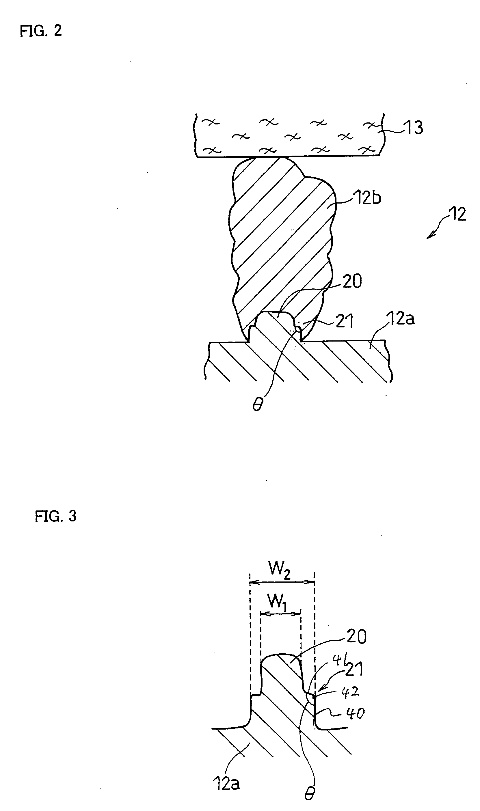
[0106]A lithium ion secondary battery of the invention was produced in the same manner as in Example 1 except that a negative electrode current collector was produced as follows.

[0107]A 6-μm thick dry film resist (trade name: PHOTEC RY-3300, available from Hitachi Chemical Company, Ltd.) was attached to the surface of a copper alloy foil (trade name HCL-02Z, available from Hitachi Cable Ltd.). Also, 8-μm diameter circular dots were printed on a resin mask. The circular dots were arranged in the close-packed arrangement at a center-to-center distance of 20 μm. This resin mask was placed on the dry film resist, irradiated with i rays using a collimated light aligner, and developed with a 1 wt % sodium carbonate aqueous solution to form a resist pattern. Next, copper protrusions were formed in the openings of the resist by a plating method. The copper alloy foil with the resist pattern was immersed as the cathode in a copper sulfate aqueous solution containing 270 g / liter of copper (II...

example 4

[0108]In the same manner as in Comparative Example 1, a copper alloy foil with circular protrusions (first protrusions) of 12 μm in diameter and 8 μm in height on the surface was prepared. These circular protrusions were arranged in the close-packed arrangement at an axis-to-axis distance of 20 μm on the surface of the copper alloy foil. This copper alloy foil was immersed in a copper sulfate aqueous solution containing 47 g / liter of copper (II) sulfate pentahydrate and 100 g / liter of sulfuric acid, and was plated at a current density of 30 A / dm2 and a liquid temperature of 50%. As a result, second protrusions (separation-stopping areas) were formed in the side faces of the circular protrusions in the circumferential direction. Further, this copper alloy foil was immersed in a copper sulfate aqueous solution containing 235 g / liter of copper (II) sulfate pentahydrate and 100 g / liter of sulfuric acid, and was plated at a current density of 3 A / dm2 and a liquid temperature of 50° C. to...


PUM


Abstract

A negative electrode including a negative electrode current collector, first protrusions on a surface of the negative electrode current collector, a separation-stopping area on at least a part of a surface of each first protrusion, and a negative electrode active material layer including a negative electrode active material and formed on at least a top face of the first protrusion. This structure suppresses the separation of the negative electrode active material layer from the negative electrode current collector, the degradation of the current collecting ability, and the deformation of the negative electrode itself. A lithium ion secondary battery including this negative electrode has a high battery capacity, a high energy density, and an excellent charge/discharge cycle characteristic, and is capable of stably maintaining a high power over an extended period of time.

Description

FIELD OF THE INVENTION[0001]The invention relates to a negative electrode for a lithium ion secondary battery and a lithium ion secondary battery. More particularly, the invention mainly relates to improvements in the negative electrode for a lithium ion secondary battery.BACKGROUND OF THE INVENTION[0002]With the recent, remarkable widespread use of portable electronic devices, such as personal computers, cellular phones, and mobile devices, there is an increasing demand for batteries used as the power source for portable electronic devices. The batteries for use in portable electronic devices are required to operate at room temperature, have a large battery capacity, and offer a high energy density and an excellent charge / discharge cycle characteristic. One such battery is a lithium ion secondary battery which includes a positive electrode including a positive electrode active material capable of reversibly absorbing and desorbing lithium ions, a negative electrode including a nega...

Claims


Application Information

Patent Timeline
IPC IPC(8): H01M4/24H01M2/14H01M4/02H01M4/13H01M4/64H01M10/0525
CPCH01M4/661H01M4/70H01M4/742Y02E60/122H01M2004/025H01M2004/027H01M10/0525Y02E60/10H01M4/02H01M10/02
Inventor KOGETSU, YASUTAKAIWAMOTO, KAZUYAYAMAMOTO, TAISUKE
Owner PANASONIC CORP
Why Eureka
Try Eureka