Method and Apparatus for Computer-Assisted Femoral Head Resurfacing

a computer-assisted, femoral head technology, applied in the field of computer-assisted surgery, can solve the problems of bone resorption and degeneration, pulmonary occlusion, less predictable outcomes of younger and more active patients, etc., to reduce femoral neck notching/fracture, improve the outcome of resurfacing, and reduce the complication rate

Inactive Publication Date: 2008-09-04
ORTHOSOFT ULC
View PDF11 Cites 42 Cited by
  • Summary
  • Abstract
  • Description
  • Claims
  • Application Information

AI Technical Summary

Benefits of technology

[0011]Proposed herein is a method of computer-assisted navigation in conjunction with novel apparatus that may be used to optimally prepare the femoral head and place the guide pin and component. This method is an improvement in outcomes of resurfacing by decreasing complication rates (reduced femoral neck notching / fracture rate and avascular necrosis), improving component placement and hip range of motion / kinematics, decreasing length of time in the operating room, allowing surgeons to use the smallest size femoral head component safely possible for each patient (and therefore minimize unnecessary acetabular bone removal for acetabular instrumentation), and creating opportunities to perform resurfacing through less invasive surgical incisions. The approach may be applied to other bones such as the humerus where appropriate reference points may be identified on preoperative radiographs.
[0012]In accordance with one aspect of the invention, there is provided a registration tool for registering the position of a bone in space during surgery. The registration tool may have a flat planar first surface, a flat planar second surface oriented at a selected angle to the first surface, with the first surface adapted to contact at least two preselected anatomical features of the bone and the second surface adapted to contact at least three preselected anatomical features of the bone, thereby constraining the registration tool in at least 5 degrees of freedom relative to the bone, and means for sensing and recording the position of the registration tool in space.

Problems solved by technology

However, the results in younger and more active patients have been less predictable, especially where older reconstructive techniques and materials such as bone cement have been used.
THA procedures require a long stem to be inserted into the medullary canal, which can trigger fat emboli during surgery, potentially leading to pulmonary occlusion, and can begin a process of bone resorption and degeneration which can limit the overall life of the implant.
Despite the attractive clinical results and success, however, there continues to be a number of complications and potential concerns with the surgical technique that are unique to FHR.
In comparison to total hip arthroplasty, the surgical technique is more complex and demands higher degree of precision from the surgeon.
Pin placement is a time-consuming process in the operating room and despite the surgeon's efforts to centre the pin using intraoperative guides and calipers, the surgical technique can be unreliable [Variability of femoral positioning in hip resurfacing arthroplasty, 51st Annual Meeting of the Orthopaedic, by Shekhman M., Masri B. A., Greidanus N. V., Garbuz D. S., Duncan C. P., Anglin C., Hodgson A. J., and Inkpen K. B., Research Society, Washington, D.C., Feb. 20-23, 2005] and may result in sub-optimal component placement or notching.
In addition, malposition of the guide pin may result in oversizing the femoral head component, which may then necessitate excessive removal of acetabular bone stock for acetabular component placement.
Malposition of the femoral component may also compromise the hip's range of motion and patient satisfaction with the procedure.

Method used


Image

  • Method and Apparatus for Computer-Assisted Femoral Head Resurfacing
  • Method and Apparatus for Computer-Assisted Femoral Head Resurfacing
  • Method and Apparatus for Computer-Assisted Femoral Head Resurfacing

Examples


example 1

End-to-End Procedure

[0104]In one preferred embodiment, a surgeon utilized the apparatus and method of this invention to complete full preoperative planning, obtain required intraoperative measurements, and complete the procedure.

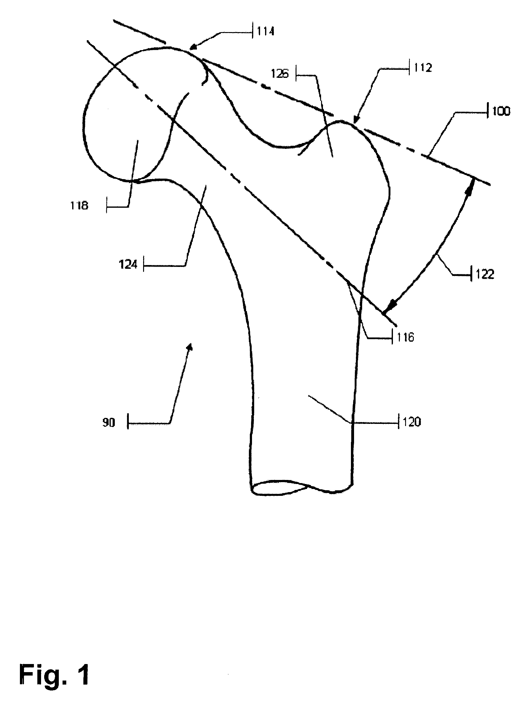
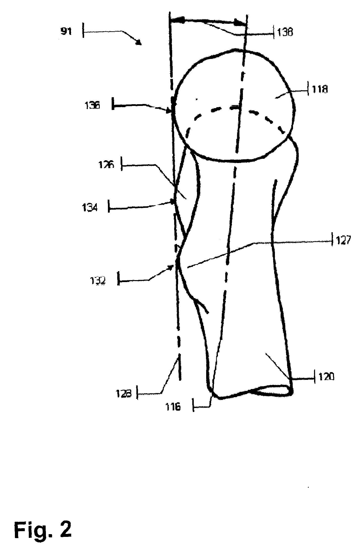
[0105]In this embodiment, a surgeon used an anteroposterior (AP) (FIG. 1) and mediolateral (ML) (FIG. 2) radiographs of the femur to draw the preoperative surgical plan. The radiographs were digitized and imported into a custom designed navigation system.

[0106]On the AP radiograph, a surgeon defined the superior reference plane based on a line connecting superior aspects of the femoral head and the greater trochanter (GT). A planned implant axis was also drawn the digitized radiograph and varus / valgus angle was measured between the superior reference plane and the planned implant axis. in accordance to well established practice. Superior and posterior reference planes were drawn on radiographs.

[0107]On the ML radiograph, a surgeon defined the posterior refer...

example 2

Cadaver and Artificial Bone Studies

[0121]An embodiment of the invention was constructed and tested on artificial bone models and cadaver bones. The latter study was performed using 5 pairs of proximal femurs in a simulated OR environment. AP and ML radiographs were taken of each bone. An expert surgeon, experienced in the operation of the mechanical device used to determine the femoral implant axis, performed the preoperative planning procedure.

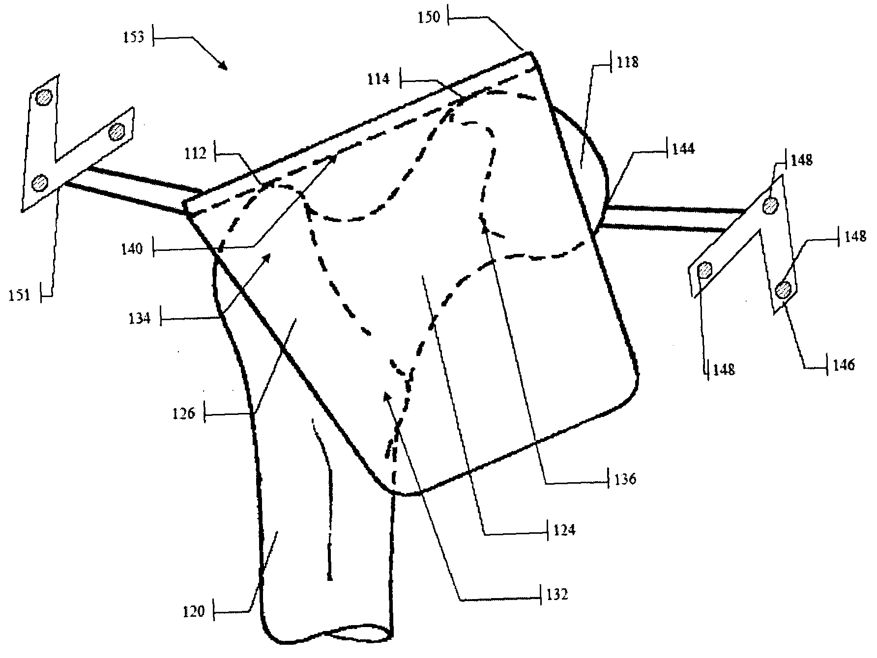
[0122]Each bone had an optical tracker attached to it (FIG. 3) and each bone was registered with the CAS system built for this embodiment. The registration proceeded by using a Reference Tool (RT) described above.

[0123]On one of each pair of femurs, a novice surgeon used the CAS system to calculate a guide pin axis at the planned angles through the centre of the narrowest point of the femoral neck. The calculated target axis for the drill guide was recorded, and the final pin position measured after the novice surgeon drove the pin. The pin w...


PUM


Abstract

A method for locating a guide wire axis on a femoral neck comprises the steps of tracking a position and orientation of a femur; registering a frame of reference with respect to the position and orientation of the femur from a first registration probe mounted onto the femur in a predetermined configuration, the frame of reference having preoperative planned data pertaining to the femoral neck; digitizing femoral neck data with respect to the position and orientation of the femur from a second registration probe positioned onto the femoral neck at desired orientations; calculating a position and orientation of the guide wire axis with respect to the position and orientation of the femur as a function of the preoperative planned data and the femoral neck data.

Description

BACKGROUND OF THE INVENTION[0001]1. Field of the Invention[0002]The present invention relates to the field of computer assisted surgery (CAS), in particular procedures for implantation and revision of artificial joint and bone components. Particular focus of the invention is on intraoperative registration of a bone, transfer of preoperatively planned geometry to bone, and intraoperative characterization of the bone. The present invention is particularly adapted for computer assisted Femoral Head Resurfacing (FHR).[0003]2. Background Art[0004]With an aging population, bone and joint deterioration due to a number of different diseases—most notably arthritis, is an increasingly common occurrence. A common procedure—total hip replacement (total hip arthroplasty—THA)—has been successfully used in older patients with predictable and durable results. Some of the initial issues in regards to implant mobility and wear and tear have been overcome with the advent of new generation of implants ...

Claims


Application Information

Patent Timeline
Patent Type & Authority Applications(United States)
IPC IPC(8): A61B5/103A61B17/56A61F2/36
CPCA61B5/064A61B17/1707A61B17/1721A61B17/175A61B19/50A61B19/5244A61F2002/4632A61B2019/461A61B2019/508A61B2019/5255A61B2019/5268A61F2/3603A61B19/56A61B34/10A61B34/20A61B34/25A61B2034/108A61B2034/2055A61B2034/2068A61B2090/061
Inventor HODGSON, ANTONYINKPEN, KEVIN BRYANTANGLIN, CAROLYN
Owner ORTHOSOFT ULC
Why Eureka
Try Eureka