Dynamic film thickness control system/method and its utilization

a control system and film technology, applied in the field of dynamic film thickness control system/method, can solve the problems of large vacuum system, extremely difficult production, and difficult suitability, and achieve the effect of optimal film quality and effective

Inactive Publication Date: 2008-09-11
HERMOSA THIN FILM
View PDF9 Cites 106 Cited by
  • Summary
  • Abstract
  • Description
  • Claims
  • Application Information

AI Technical Summary

Benefits of technology

[0010]The primary objective of the invention herein is to provide a dynamic film thickness control system and method that utilizes one or more points of simultaneous control, a correspondingly movable control system, and a matching mask plate control to effectively afford control over accurate coating uniformity and thickness.
[0011]Another objective of the invention herein is to provide a dynamic film thickness control system and coating method that utilizes one or more points of simultaneous control, a correspondingly movable control system, and a matching mask plate control to effectively afford control over accurate coating uniformity and thickness, and thereby achieve optimal film quality.

Problems solved by technology

However, in the case of optical film designs having extremely high precision thickness error requirements (for example, the narrow band filter for optical fiber communications-use, having a total of about 100 layers, with each layer having an error tolerance of 0.003 percent), its suitability is extremely problematic.
Furthermore, if the said substrate is very large in dimension, (for example, two to three meters), utilizing the said coating method would require an extremely large vacuum system and incur production difficulties.
This method of correcting sputtering thickness uniformity afterwards by changing mask plate shape after sputtering completion is incapable of immediately effecting accurate correction during the sputtering process which, with regard to relatively more complex or high precision requirement optical film designs, would still have production difficulties.

Method used


Image

  • Dynamic film thickness control system/method and its utilization
  • Dynamic film thickness control system/method and its utilization
  • Dynamic film thickness control system/method and its utilization

Examples


first embodiment

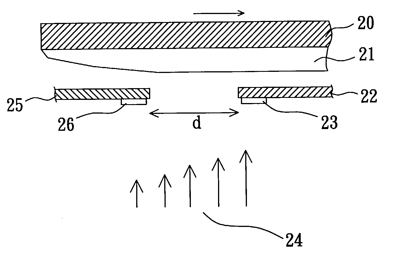
[0031]the dynamic film thickness control system of the invention herein, as indicated in FIG. 4, consists of a mask plate 22 situated at the lower extent of a substrate 20 and a quartz crystal 23 attached to bottom surface at the end of the said mask plate 22. The thickness of the film 21 deposited onto the substrate 20 is exaggerated in the drawing for purposes of clarity, wherein the arrows 24 indicate the average coating speed rate, the shorter or longer lengths of the arrows 24 representing slower and faster coating speed rates; the evaporation source is not shown in figure. The embodiment herein places the quartz crystal 23 at an appropriate position at the lower extent of the mask plate 22. Prior to coating, the relative thickness of the film 21 on each zone of the substrate 20 can be ascertained by a computer-simulated calculation or actual measurement when the mask plate 22 in not in place. During the actual coating thereafter, the mask plate 22 is moved towards the slower e...

second embodiment

[0032]Furthermore, although some coating systems such as cathodic arc plasma deposition having magnetic fields that directionally ions to eliminate large particles or anodic plasma deposition that produce large volumes of plasma have numerous advantages, but the film thickness is difficult to control. the invention herein solves the said problem and, as indicated in FIG. 5, consists of a second mask plate 25 and a second quartz crystal 26 at one side of a first mask plate 22 in FIG. 4. As such, the first quartz crystal 23 and the second quartz crystal 26 are at two positions of coating speed rate, with the movable first mask plate 22 and second mask plate 25 governing the distance d between the two positions to thereby control the thickness of the film 21 deposited on the substrate 20. If this control system is utilized in a continuous coating system, since the first and second quartz crystals 23 and 26 lose accuracy when coating is excessively thick, a movable cover plate, cover, o...

third embodiment

[0033]If the deposition of a higher precision optical film is needed, the invention herein provides a third embodiment control system which, as indicated in FIG. 6, consists of a mask plate 32 situated at the lower extent of a substrate 30; a first detector 33 is utilized to measure light rays penetrating through the substrate 30 and film 31, with a second detector 34 measuring the light rays reflected from the substrate 30; the long and short arrows 37 indicate the rapidity and slowness of the coating speed rate and the vapor source is not shown in the drawing. The light source 36 of the control system embodiment herein is separately situated at a window 38 outside the vacuum system, enabling the light rays of the light source 36 to be externally projected through the window 38 and the transparent substrate 30 for the execution of optical control, without requiring the additional installation of an optical test piece. The said second sensor 34 is situated outside the vacuum system ...


PUM

PropertyMeasurementUnit
thicknessaaaaaaaaaa
reflection rateaaaaaaaaaa
transparentaaaaaaaaaa

Abstract

A dynamic film thickness control system / method and its utilization consisting of a minimum of one mask plate arranged between a substrate and a vapor source. A film thickness control device is utilized for real-time control over deposited film thickness and gradually moves the mask plate according to the film thickness control value acquired by the film thickness control device, enabling the mask plate to mask film zones on the said substrate to achieve the film thickness of a design objective. When the required zones of deposition are masked, the deposition of a particular film layer is completed.

Description

BACKGROUND OF THE INVENTION[0001]1) Field of the Invention[0002]The invention herein relates to film thickness control in coating systems, specifically a dynamic film thickness control system / method and its utilization.[0003]2) Description of the Prior Art[0004]Due to significant technological progress in recent years, the requirements of uniform film thickness have become considerably stringent. For example, the film currently utilized on aircraft cockpits to reflect electromagnetic waves is a single layer transparent, conductive oxide film such as indium-tin oxide or indium-zinc oxide film. The precision requirements of which are not great; however, these will be further improved into higher precision multi-layer optical films in the future as technology advances.[0005]Referring to FIG. 1, an example conventional coating system is comprised of an optical thickness monitoring light source assembly 1 (referred to hereafter as the light source), an optical control test glass 2 (refer...

Claims


Application Information

Patent Timeline
Patent Type & Authority Applications(United States)
IPC IPC(8): C23C14/54C23C16/00B05C11/00C23C16/52G01B11/02G01B11/06G01B15/02
CPCC23C14/042C23C14/044C23C14/24G01B11/0683C23C14/3464C23C14/546C23C14/547C23C14/30
Inventor LING, KOW-JEJUANG, JIUNN-SHIUH
Owner HERMOSA THIN FILM
Why Eureka
Try Eureka