Dynamic film thickness control system/method and its utilization
a control system and film technology, applied in the direction of ion implantation coating, chemical vapor deposition coating, coating, etc., can solve the problems of large vacuum system, high cost, and inconvenient production, and achieve the effect of optimal film quality and effective
- Summary
- Abstract
- Description
- Claims
- Application Information
AI Technical Summary
Benefits of technology
Problems solved by technology
Method used
Image
Examples
first embodiment
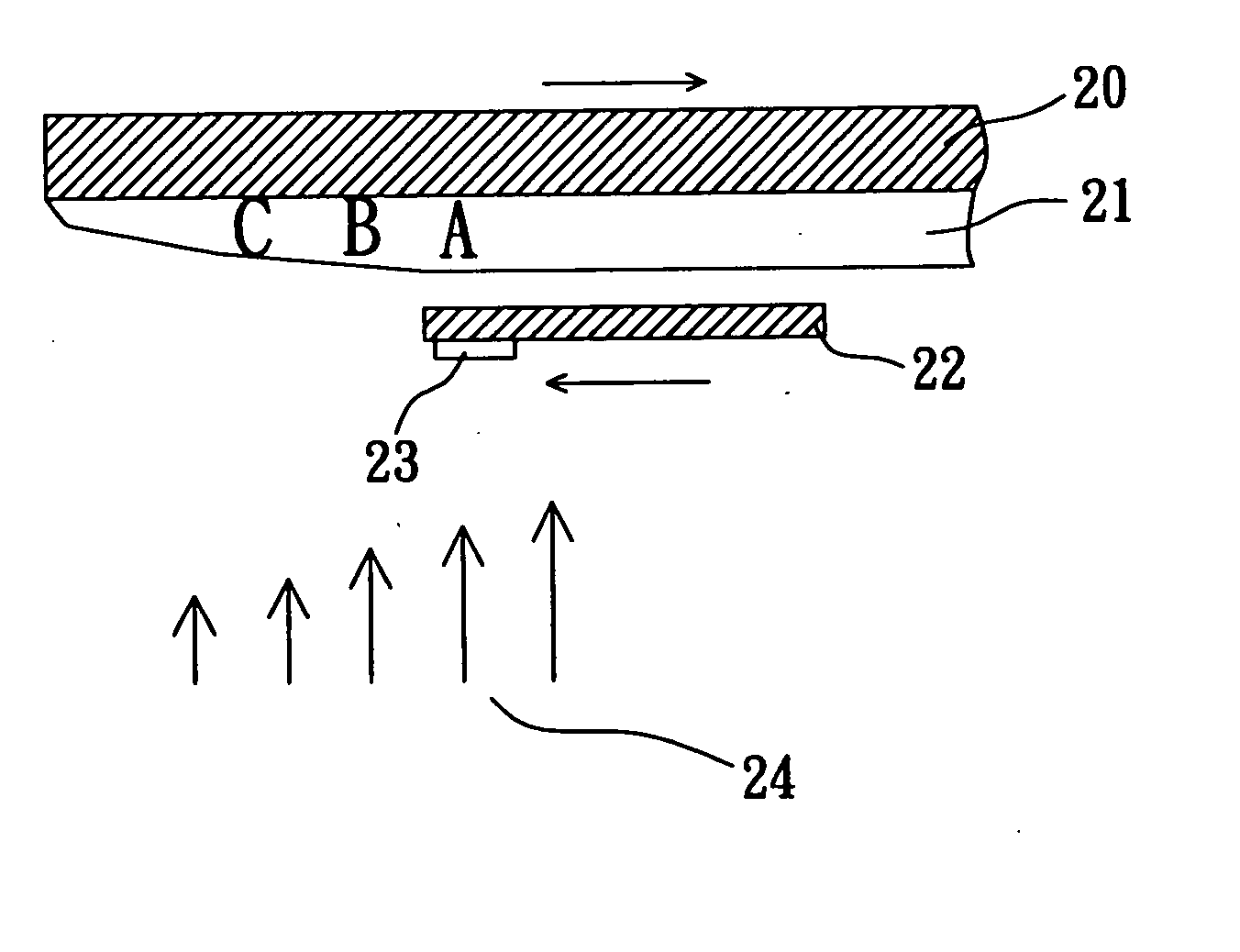
[0031] the dynamic film thickness control system of the invention herein, as indicated in FIG. 4, consists of a mask plate 22 situated at the lower extent of a substrate 20 and a quartz crystal 23 attached to bottom surface at the end of the said mask plate 22. The thickness of the film 21 deposited onto the substrate 20 is exaggerated in the drawing for purposes of clarity, wherein the arrows 24 indicate the average coating speed rate, the shorter or longer lengths of the arrows 24 representing slower and faster coating speed rates; the evaporation source is not shown in figure. The embodiment herein places the quartz crystal 23 at an appropriate position at the lower extent of the mask plate 22. Prior to coating, the relative thickness of the film 21 on each zone of the substrate 20 can be ascertained by a computer-simulated calculation or actual measurement when the mask plate 22 in not in place. During the actual coating thereafter, the mask plate 22 is moved towards the slower ...
second embodiment
[0032] Furthermore, although some coating systems such as cathodic arc plasma deposition having magnetic fields that directionally ions to eliminate large particles or anodic plasma deposition that produce large volumes of plasma have numerous advantages, but the film thickness is difficult to control. the invention herein solves the said problem and, as indicated in FIG. 5, consists of a second mask plate 25 and a second quartz crystal 26 at one side of a first mask plate 22 in FIG. 4. As such, the first quartz crystal 23 and the second quartz crystal 26 are at two positions of coating speed rate, with the movable first mask plate 22 and second mask plate 25 governing the distance d between the two positions to thereby control the thickness of the film 21 deposited on the substrate 20. If this control system is utilized in a continuous coating system, since the first and second quartz crystals 23 and 26 lose accuracy when coating is excessively thick, a movable cover plate, cover, ...
third embodiment
[0033] If the deposition of a higher precision optical film is needed, the invention herein provides a third embodiment control system which, as indicated in FIG. 6, consists of a mask plate 32 situated at the lower extent of a substrate 30; a first detector 33 is utilized to measure light rays penetrating through the substrate 30 and film 31, with a second detector 34 measuring the light rays reflected from the substrate 30; the long and short arrows 37 indicate the rapidity and slowness of the coating speed rate and the vapor source is not shown in the drawing. The light source 36 of the control system embodiment herein is separately situated at a window 38 outside the vacuum system, enabling the light rays of the light source 36 to be externally projected through the window 38 and the transparent substrate 30 for the execution of optical control, without requiring the additional installation of an optical test piece. The said second sensor 34 is situated outside the vacuum system...
PUM
| Property | Measurement | Unit |
|---|---|---|
| Thickness | aaaaa | aaaaa |
Abstract
Description
Claims
Application Information
 - R&D
- Intellectual Property
- Life Sciences
- Materials
- Tech Scout
- Unparalleled Data Quality
- Higher Quality Content
- 60% Fewer Hallucinations
Browse by: Latest US Patents, China's latest patents, Technical Efficacy Thesaurus, Application Domain, Technology Topic, Popular Technical Reports.
© 2025 PatSnap. All rights reserved.Legal|Privacy policy|Modern Slavery Act Transparency Statement|Sitemap|About US| Contact US: help@patsnap.com


