Method and equipment for monitoring syntrophic relations in a biological process fluid

a biological process fluid and syntrophic relationship technology, applied in water treatment parameter control, water/sludge/sewage treatment, component separation, etc., can solve the problem that the plant operator was not able to detect the overloading of the reactor b>3

Inactive Publication Date: 2008-09-11
PIND PETER FRODE +1
View PDF1 Cites 0 Cited by
  • Summary
  • Abstract
  • Description
  • Claims
  • Application Information

AI Technical Summary

Benefits of technology

[0012]In general, the present invention provides a method and an equipment for monitoring the syntrophic relations between different parts of a bacterial consortium in the process fluid of a biological process plant, such as a biological gas plant or waste water treatment plant, through an accurate measurement of the content of the individual volatile fatty acids in consecutive samples of the process fluid, employing small quantities of process fluid. The present invention is particularly useful in cases where the biological process is an anaerobic digestion in a biological gas plant or a waste water treatment plant. More particularly, the present invention provides a solution to the problems presently faced when trying to monitor the process state of an anaerobic digestion, e.g. in waste water treatment and biological gas production, through an analysis, which makes it possible to monitor the syntrophic relations between different parts of the bacterial consortium in the process fluid, trough an accurate on-line measurement of the content of the individual volatile fatty acids in consecutive samples.

Problems solved by technology

The gas production had been increasing from the beginning of the period from both reactors and the measurements of the total content of VFA done with currently available methodology and equipment, could not detect any increase of VFA (refer to FIG. 2) due to the inaccuracy of the method used.
Hence, the plant operator was not able to detect the overloading of reactor 3 with the currently available methodology.

Method used


Image

  • Method and equipment for monitoring syntrophic relations in a biological process fluid
  • Method and equipment for monitoring syntrophic relations in a biological process fluid
  • Method and equipment for monitoring syntrophic relations in a biological process fluid

Examples


example

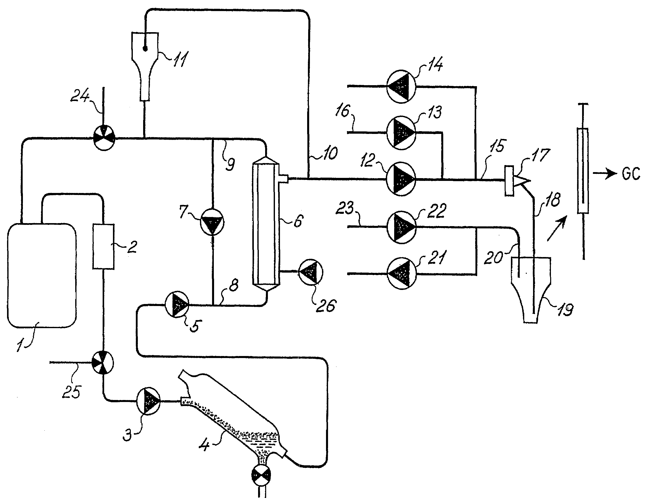
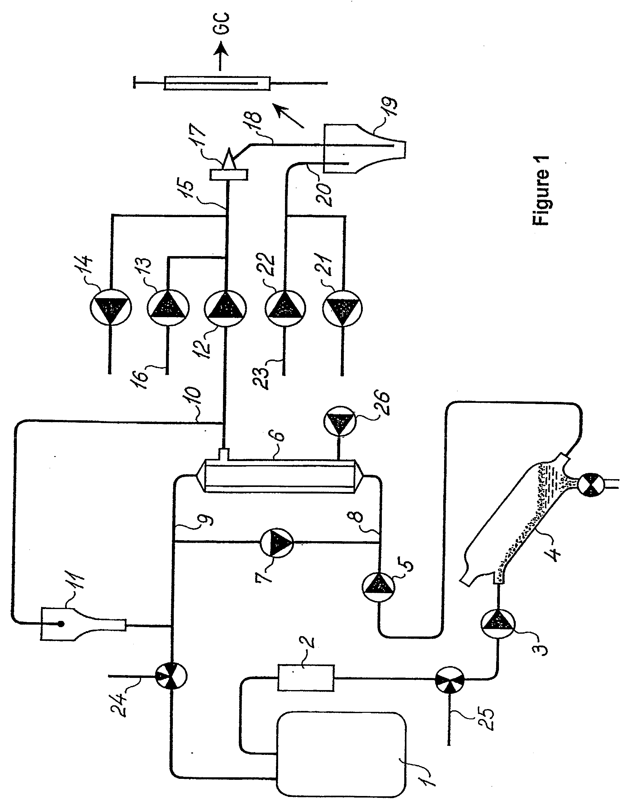
[0064]A preferred embodiment of the equipment of the present invention as described above has been tested on a full scale biogas plant in Snertinge, Denmark. The biogas plant in question treats app. 105 ton of manure and 25 ton of mixed industrial waste per day in three 1000 m3 reactors each having an active volume of app 900 m3.

[0065]Testing:

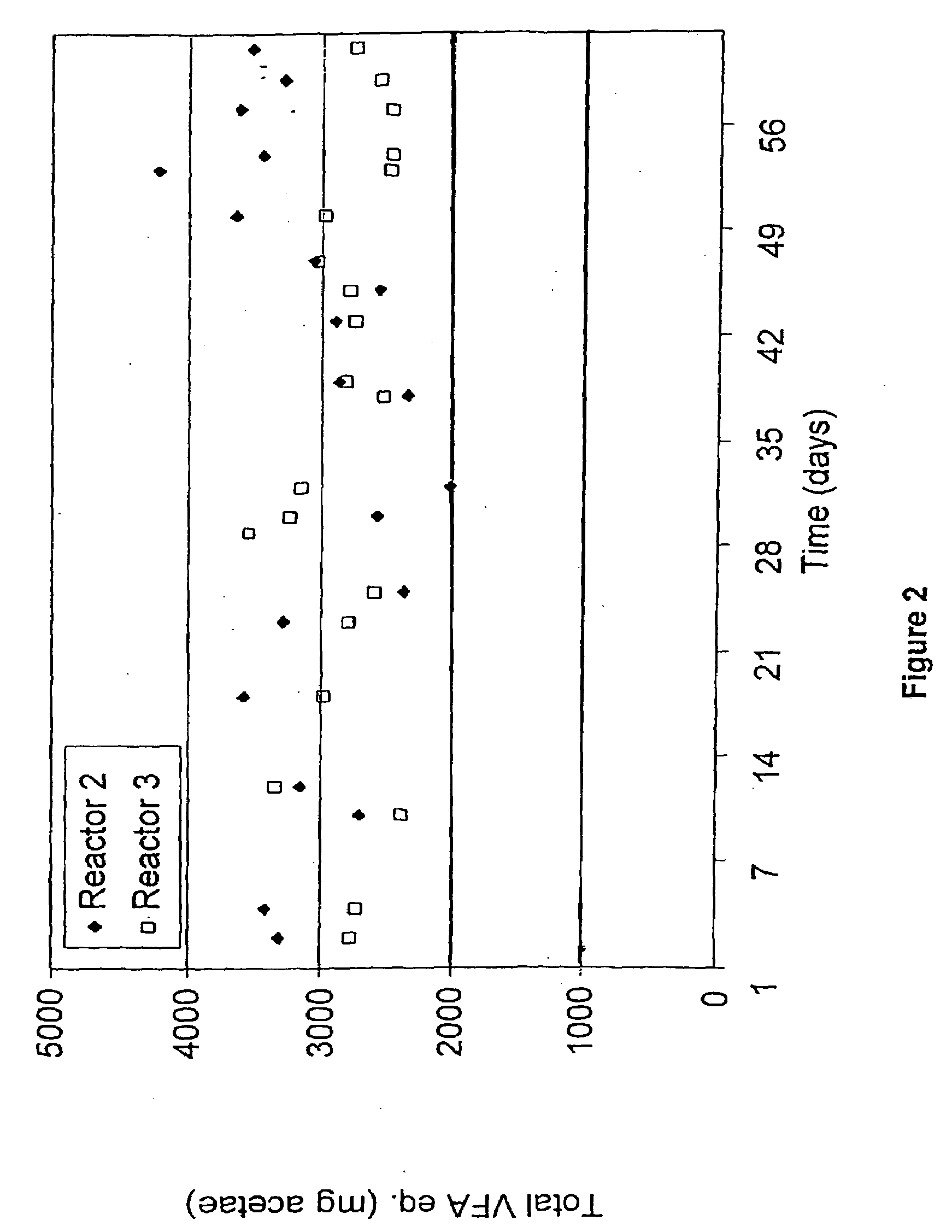
[0066]The equipment of the present invention was placed on a recirculation loop used for two of the reactors (Reactor 2 and 3) each having a hydraulic retention time of 13.3 days. A test period lasting app. one week was used to optimize system configuration.

[0067]Setup:

[0068]In order to maximally stress the equipment of the present invention measurements were taken every 15 min. The filter system was cleaned with hot water every second day for a period of 1-2 hours and septa and liner in the GC was changed at the same time. Just prior to the measuring period, the plant operator had initiated a slow increase in the reactor temperature to elevate...


PUM


Abstract

A method and an equipment for monitoring the syntrophic relations between different parts of a bacterial consortium in the process fluid of a biological process plant, such as a biological gas plant or waste water treatment plant, through a chromatographic measurement of the content of the individual volatile fatty acids in consecutive samples of the process fluid, the samples being acidified and filtered prior to the chromatographic separation

Description

FIELD OF THE INVENTION[0001]The present invention relates to a method and an equipment for monitoring syntrophic relations in a biological process fluid. More specifically it relates to a method for monitoring the syntrophic relations between different parts of the bacterial consortium in the process fluid of a biological process plant, such as a biological gas plant or waste water treatment plant and an equipment for use in such a method.BACKGROUND OF THE INVENTION[0002]Increasing industrial application of biological process fluids, such as in waste water treatment and biogas production, has resulted in a need for development of reliable methods for evaluation and control of the anaerobic digestion process.[0003]Monitoring of the process first of all requires access to a suitable parameter reflecting the metabolic state of the process. Secondly, it requires a system providing reliable determination of this process parameter in order to obtain efficient control, with the shortest po...

Claims


Application Information

Patent Timeline
IPC IPC(8): B01D15/08B01D53/84C02F3/00G01N30/14
CPCB01D53/84C02F3/006Y10T436/201666G01N30/14C02F2209/12Y02A50/20
Inventor PIND, PETER FRODEAHRING, BIRGITTE KIAER
Owner PIND PETER FRODE
Why Eureka
Try Eureka