All printed solar cell array
a solar cell and substrate technology, applied in the field of photovoltaic novelty items, can solve the problems of increasing processing and use difficulty, reducing the market acceptance of products, and high raw material costs
- Summary
- Abstract
- Description
- Claims
- Application Information
AI Technical Summary
Problems solved by technology
Method used
Image
Examples
example 1
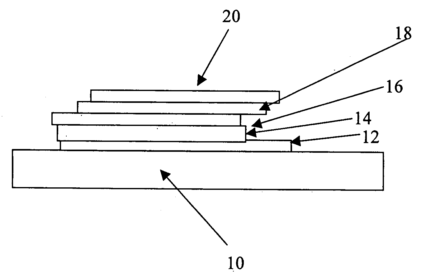
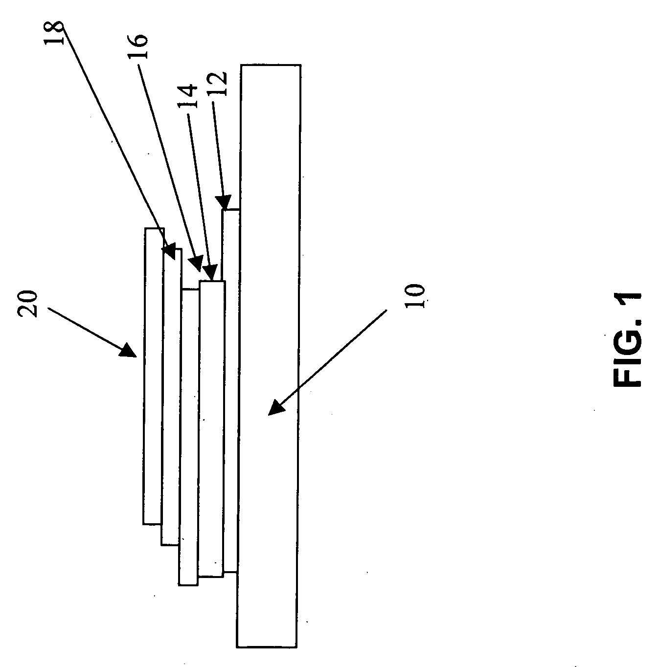
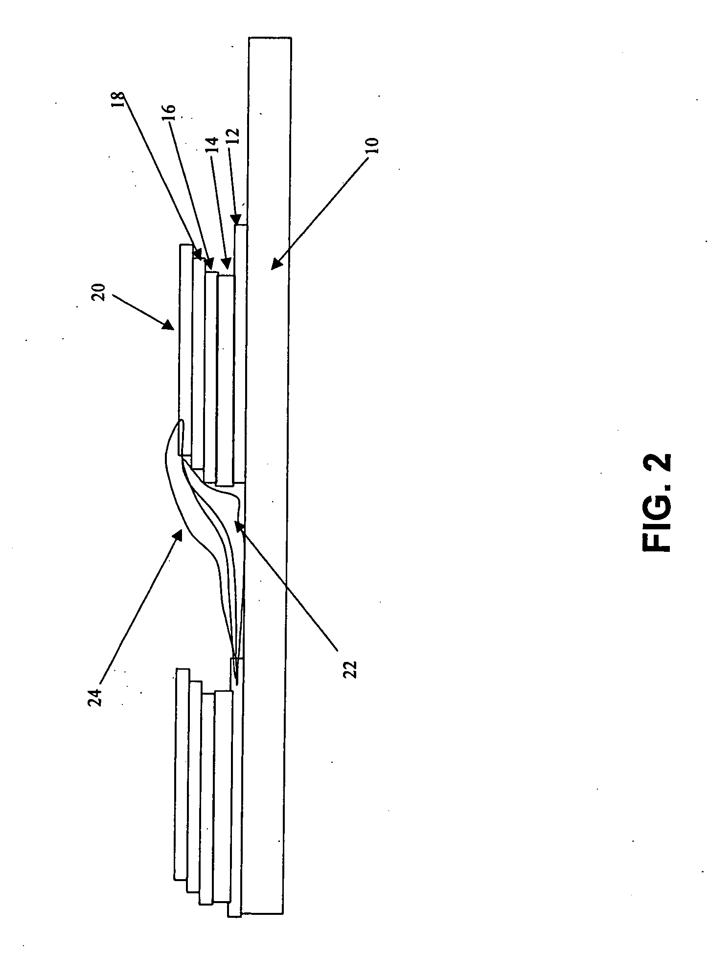
[0063]A person of ordinary skill in the art would understand screen-printing as a simple technique to overlay multi-layers of inks in registration. It may employ the use of silk screens with a photo resist mask that defines the images to be printed. An 8.5″×11″ sheet of ITO coated 3 mil Mylar (OSC50 By CPF films Canoga Park Calif.) was used as the substrate. It had a conductivity of 50Ω / cm and transparency of over 85% in the visible range. A portion of the ITO was removed, using a focused beam CO2 laser from Photomachining Corp. of Derry N.H., to define isolated square areas as the anodes (see FIG. 6).
[0064]The next layer; n-type material, incorporated a dispersion of TiO2 particles (P25 from Deggusa AG) in an acrylic resin binder (BT26 from NeoResin Wilmington Del.). The viscosity was adjusted to 10,000 cp using Rheolate 288 from Elementis Specialties Hightstown N.J. The ink was printed through a screen (320 mesh) that defined isolated square areas that registered directly on top o...
example 2
[0068]A person of ordinary skill in the art would recognize airbrush spray painting as a method of depositing ink patterns on surfaces. It may employ the use of stencils and a spray apparatus that is well known in the art. The substrate for this technique may be any smooth object but not necessarily flat (i.e. poles as substrate would use a “Tube stencil”).
[0069]This example used an uncoated 5 mil Mylar sheet. In this example the cell was inverted, that is, the cathode was on the bottom and the transparent anode was on top. This same configuration may have been used in Example 1 using screen printing instead, wherein the top layer would have been a transparent conductive ink rather than the ITO coated substrate with a slightly different target viscosity.
[0070]The first layer was that of a silver dispersion (3 μm mean diameter from Metalor Attleboro Mass.) in a cross-linkable acrylic co polymer dispersion (BT67 NeoResin Wilmington Del.). The ink was diluted with a solvent such as eth...
example 3
[0074]A person of ordinary skill in the art would recognize gravure as employing a smooth cylinder that has divots in it that define the printed image. Ink may be supplied to the roll and may be squeezed off with a squeegee prior to contact with the substrate to deposit ink on it only form the area with the divots. An 8 station Gravure press was used to print solar panels onto a flexible substrate. A 3 mil roll of Mylar (J102 Dupont Del.) was used as the substrate. Ink viscosities were adjusted to 200-300 cp.
[0075]The first station deposited the transparent conductive material in the same pattern as the bottom layer of the previous example depicted in FIG. 7. The ink was a dispersion of 50 nm sized ITO flakes (from Inframat Advanced Material Farmington Conn.) in an acrylic emulsion (BT187 NeoResin Wilmington Mass.). The next layer was a dispersion of 5% 20 nm ZnO powder (from Inframat Advanced material Farmington Conn.) and 95% 20 nm TiO2 powder (P25 Degussa) in an acrylic copolymer...
PUM
| Property | Measurement | Unit |
|---|---|---|
| temperatures | aaaaa | aaaaa |
| size | aaaaa | aaaaa |
| size | aaaaa | aaaaa |
Abstract
Description
Claims
Application Information
 - R&D
- Intellectual Property
- Life Sciences
- Materials
- Tech Scout
- Unparalleled Data Quality
- Higher Quality Content
- 60% Fewer Hallucinations
Browse by: Latest US Patents, China's latest patents, Technical Efficacy Thesaurus, Application Domain, Technology Topic, Popular Technical Reports.
© 2025 PatSnap. All rights reserved.Legal|Privacy policy|Modern Slavery Act Transparency Statement|Sitemap|About US| Contact US: help@patsnap.com


