Solar Cell (Sliver) Sub-Module Formation

a solar cell and sub-module technology, applied in the field of solar cell sub-modules, can solve the problems of elongated silicon slices in which elongated solar cells are formed, need careful handling, and limited scope of existing approaches to use elongated solar cells to form photovoltaic devices, and achieve the effect of substantially different voltage and current characteristics

Inactive Publication Date: 2008-09-18
AUSTRALIEN NAT UNIV
View PDF30 Cites 109 Cited by
  • Summary
  • Abstract
  • Description
  • Claims
  • Application Information

AI Technical Summary

Benefits of technology

[0126]The pressure on the stack is preferably selected to ensure that the leading edge of the bottom sliver solar cell engages the far side of the groove or slot wall in the alignment jig. Continued pressure on the stack ensures that the bottom-most sliver solar cell rests flat on the bottom of the groove or slot in the alignment jig. Once the sliver solar cell is resting flat on the bottom of the groove, and held there by pressure transferred from the adjacent sliver solar cell in the stack, the rear gate of the dispensing cassette can clear the rear edge and top face of the retained sliver solar cell. This sequence of removal of sliver cells from the stack in the dispensing cassette, and placement of removed sliver cells in the grooves or slots in the alignment jig is repeated for all grooves or slots in the array-forming alignment jig as the dispensing cassette continues a transit of the metal or rigid plastic or polymer alignment jig until all grooves or slots are filled. A trailing double-ended ski mechanism retains the sliver solar cells in the grooves to prevent them flipping or jumping as the rear gate of the sliver cell dispensing cassette and trailing edge of the adjacent sliver solar cell retained in the sliver cell dispensing cassette slips over the front edge of the sliver solar cell retained in in the groove or slot of the alignment jig.
[0127]It will be apparent that in this form of the invention the sliver solar cells are removed from the dispensing cassette and retained in a regular planar array or repeating pattern of spacing between the sliver solar cells within the alignment jig without the requirement for individually locating, engaging, and removing single sliver solar cells as is the case with a conventional pick and place process.
[0128]Movement of the sliver cell dispensing cassette continues until the number of sliver solar cells required to form a sliver raft, sliver mesh raft, or sliver boat sub-module assembly array have been dispensed into the grooves or slots in the alignment jig. In one form of the invention, cross beams, prepared electrical interconnection wires, or substrates that are required to complete the sliver raft, sliver mesh raft, or sliver boat sub-module array are previously prepared with adhesive in areas where the cross-beam or substrate surface coincides with the sliver solar cell surface. The cross-beams, prepared and bent wires for electrical interconnections, or substrates required to complete the sliver raft, sliver mesh raft, or sliver boat assembly can be presented to the top surface of the array and bonded in place to provide mechanical stability with conventional adhesives such as SMT IR-130 heat-curable adhesive, or bonded in place using conductive epoxies such as heat curable Electrodag 5915 to provide mechanical stability and electrical interconnection, or soldered in place using a conventional reflow operation in order to provide mechanical support and electrical interconnection. More preferably, and advantageously, a selective wave solder process can be used in order to provide mechanical support and electrical interconnection without the requirement for dispensing or screen printing solder paste for subsequent reflow.

Problems solved by technology

The elongate slices of silicon in which elongate solar cells are formed are fragile and need careful handling, in particular during separation from the host wafer, testing, sorting and binning, storage, mounting and electrical interconnection.
Existing approaches to using elongate solar cells to form photovoltaic devices have been limited in scope.
A significant difficulty with forming a photovoltaic device using this technique is the requirement for relatively precise placement and electrical interconnection of a relatively large number of elongate cells over a relatively large area to form an array with a similar power output to a standard solar module of similar area, but with the possibility of substantially different voltage and current characteristics.
Additionally, conventional pick-and-place processes, which are generally designed for the assembly of high value, small-sized items over relatively small substrate areas, can be too slow and complex to be economically viable when modified to cover large area substrates.
Alternatively, a high-speed assembly system with acceptable throughput would necessarily be expensive, require precision manufacturing and control systems, and would almost certainly have a limited practical life due to the wear and tear of handling large numbers of small elongate solar cells at high speeds over the area of a conventional solar module assembly.
However, elongate solar cells can be bifacial (i.e., have two opposing optically active faces), and can also be perfectly symmetrical in physical form, making visual determination of their polarity impossible.
Elongate solar cells with a very large aspect ratio, can readily warp or bend if they are thin enough, but at the same time are quite brittle when subjected to localized stress and may fracture or become damaged during separation, handling, testing, binning, and assembly.
Another difficulty with elongate solar cells is that they can easily be mis-oriented about their length axis during separation and handling.
Mis-oriented elongate bifacial solar cells can therefore inadvertently be incorporated in the module in an orientation that forces them to operate in reverse bias, which would reduce the module output and has the potential to destroy the cell and / or the module.
For various reasons, it is not convenient to entirely encapsulate elongate solar cells in the standard manner described above.
However, this arrangement makes it difficult to form reliable electrical connections between elongate cells.
Each conventional cell is 2 cm to 5 cm wide and 20 to 40 cells are connected in series along the length of the receiver which has a length of 1-2 m. The uniformity of the light is generally good along the length of the receiver but poor in the transverse direction.
However, the series interconnection with this conventional system occupies a significant area.
As a consequence, significant series resistance losses arise.

Method used


Image

  • Solar Cell (Sliver) Sub-Module Formation
  • Solar Cell (Sliver) Sub-Module Formation
  • Solar Cell (Sliver) Sub-Module Formation

Examples


Embodiment Construction

Sub-Module Formation

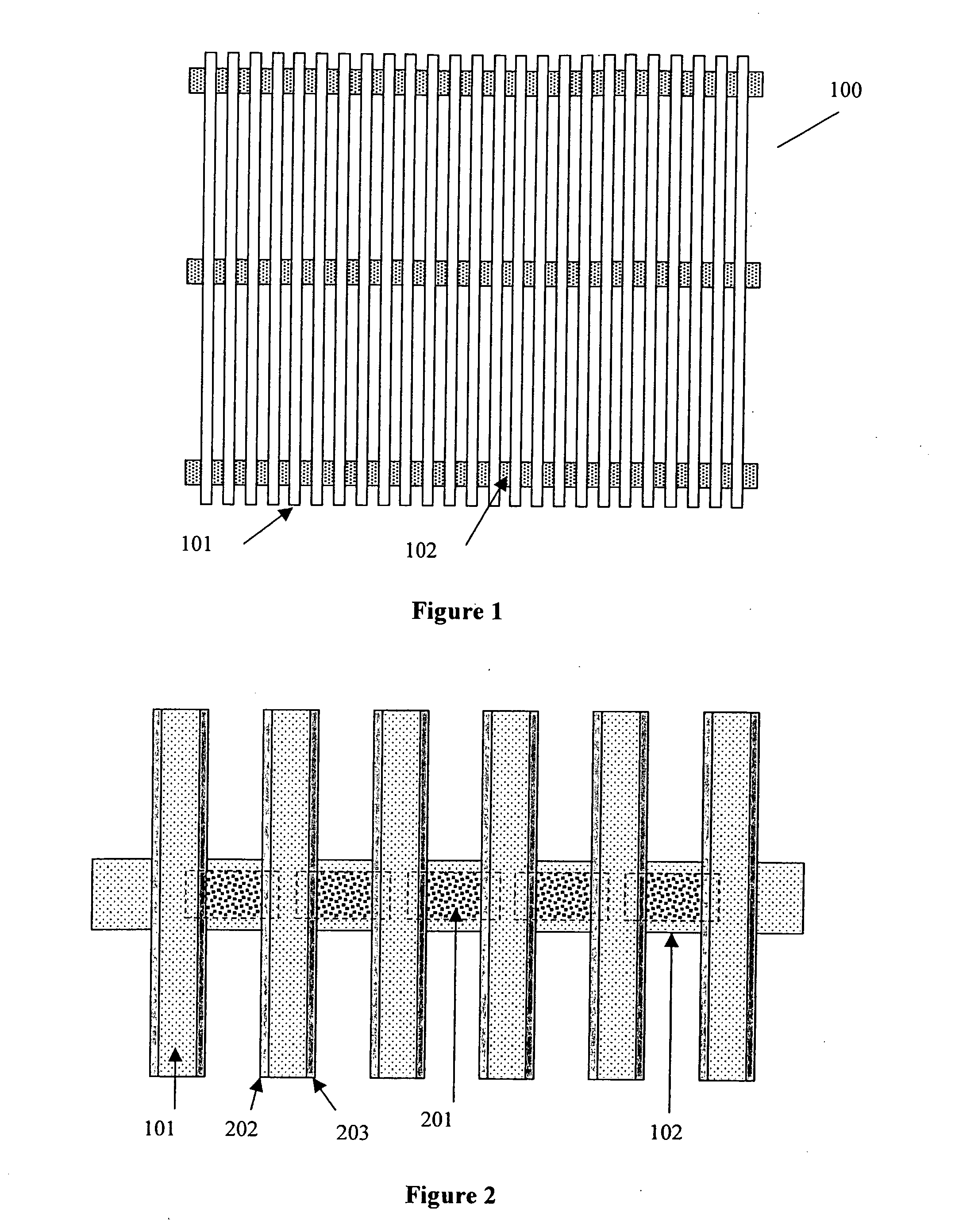
[0235]Referring to FIG. 1, elongate solar cells 101 and crossbeams 102 are assembled to form a sub-module referred to herein as a “raft” sub-module 100. Although the spacing between adjacent elongate solar cells 101 is shown in FIG. 1 as being approximately equal to the width of each cell, in the general case the spacing between cells 101 can range from zero (whereby adjacent cells abut one another) up to several times the width of each cell. The crossbeams 102 can be made of any material and are preferably thin, not electrically conductive (or are coated with an insulating material) and can be readily and selectively coated with conductive tracks. For example, thin strips of silicon from 30 microns to 100 microns thick, 1 to 3 mm wide, and 2 to 20 cm long are particularly suitable for the crossbeams 102. The cells 101 are mechanically adhered to the crossbeams 102 using adhesive or metal solder or conductive epoxy or a similar material.

[0236]Referring to FIG. 2,...


PUM

PropertyMeasurementUnit
thickaaaaaaaaaa
thickaaaaaaaaaa
diameteraaaaaaaaaa

Abstract

A solar cell sub-module (100) for a photovoltaic device, including a plurality of elongate solar cells (slivers) (101) mounted in a structure that maintains the elongate solar cells in a longitudinally parallel and generally coplanar configuration, the structure providing one or more conductive pathways (201) electrically interconnecting the elongate solar cells (101). Also claimed are inventions related to releasing elongate substrate from a wafer frame; providing a plurality of mutually spaced elongate storage bins with a particular spacing; dispensing elongate solar cells into an alignment jig and attaching the cells to a substrate; engaging a length of electrical interconnect with an engagement tool having spaced engagement sections and applying a cutting tool; forming an electrical connection in a photovoltaic module with a conductor defining an indirect path between locations to compensate for thermal expansion; maintaining the solar cell orientation of sliver solar cells when releasing them from a wafer frame; engaging only opposing faces of elongate substrates, interconnected by a wafer frame, when releasing them; storing elongate substrate in a stacked configuration with a translation mechanism.

Description

FIELD OF THE INVENTION[0001]The present invention relates to a solar cell sub-module incorporating elongate solar cells and a method of forming the solar cell sub-module, and in particular to a solar cell sub-module for a photovoltaic device, a method of forming a solar cell sub-module for a photovoltaic device, a substrate release process, an elongate substrate dispensing process, a process for forming a solar cell sub-module for a photovoltaic device, an elongate substrate handling system, a process for forming a solar cell sub-module for a photovoltaic device, a process for forming an electrical connection in a photovoltaic module, a process for forming an electrical connector for a photovoltaic module, a process for forming electrical connections between sliver cells in a photovoltaic module, an electrical connector for a photovoltaic module, a system for forming electrical connectors for a photovoltaic module, a sliver removal process, a sliver removal apparatus, a sliver remov...

Claims


Application Information

Patent Timeline
Patent Type & Authority Applications(United States)
IPC IPC(8): H01L31/048H01L31/052H01L31/18
CPCH01L24/80Y10T29/49117H01L2924/01013H01L2924/01029H01L2924/01077H01L2924/01082H01L2924/09701H01L2924/10329Y02E10/52H01L2924/01005H01L2924/01006H01L2924/01023H01L2924/01033H01L2924/01047H01L2924/01075H01L2924/014B28D1/005H01L31/0201H01L31/035281H01L31/042H01L31/0508H01L31/0512H01L31/0516H01L31/0521H01L31/188H01L2924/351H01L2924/12036Y02E10/50H01L2924/00
Inventor EVERETT, VERNIE ALLANBLAKERS, ANDREW WILLIAM
Owner AUSTRALIEN NAT UNIV
Why Eureka
Try Eureka