Systems and methods for improving luminescent concentrator performance

a luminescent concentrator and performance technology, applied in the field of photovoltaics, can solve the problems of limited loss reduction, large loss probability, and limited loss reduction, and achieve the effect of improving the performance of the luminescent concentrator, broad transmission of incident sunlight, and broad application prospects

Inactive Publication Date: 2008-09-18
INTEMATIX
View PDF11 Cites 94 Cited by
  • Summary
  • Abstract
  • Description
  • Claims
  • Application Information

AI Technical Summary

Benefits of technology

[0008]Embodiments of the present invention are directed to systems and methods for improving the performance of a luminescent concentrator. The performance of a luminescent concentrator according this invention may be greatly improved by incorporating a reflector capable of blocking re-emitted photons by the luminescent material used to make frequency down conversion with a narrow reflection band while allowing broad transmission of incident sunlight. The reflection band of the reflector that spectrally matches to the bandwidth of re-emission from the lum

Problems solved by technology

This is primarily because the electrons generated by short-wavelength incident light have a higher concentration at the vicinity of the surface, and therefore a larger probability of loss before they ca

Method used


Image

  • Systems and methods for improving luminescent concentrator performance
  • Systems and methods for improving luminescent concentrator performance
  • Systems and methods for improving luminescent concentrator performance

Examples


Embodiment Construction

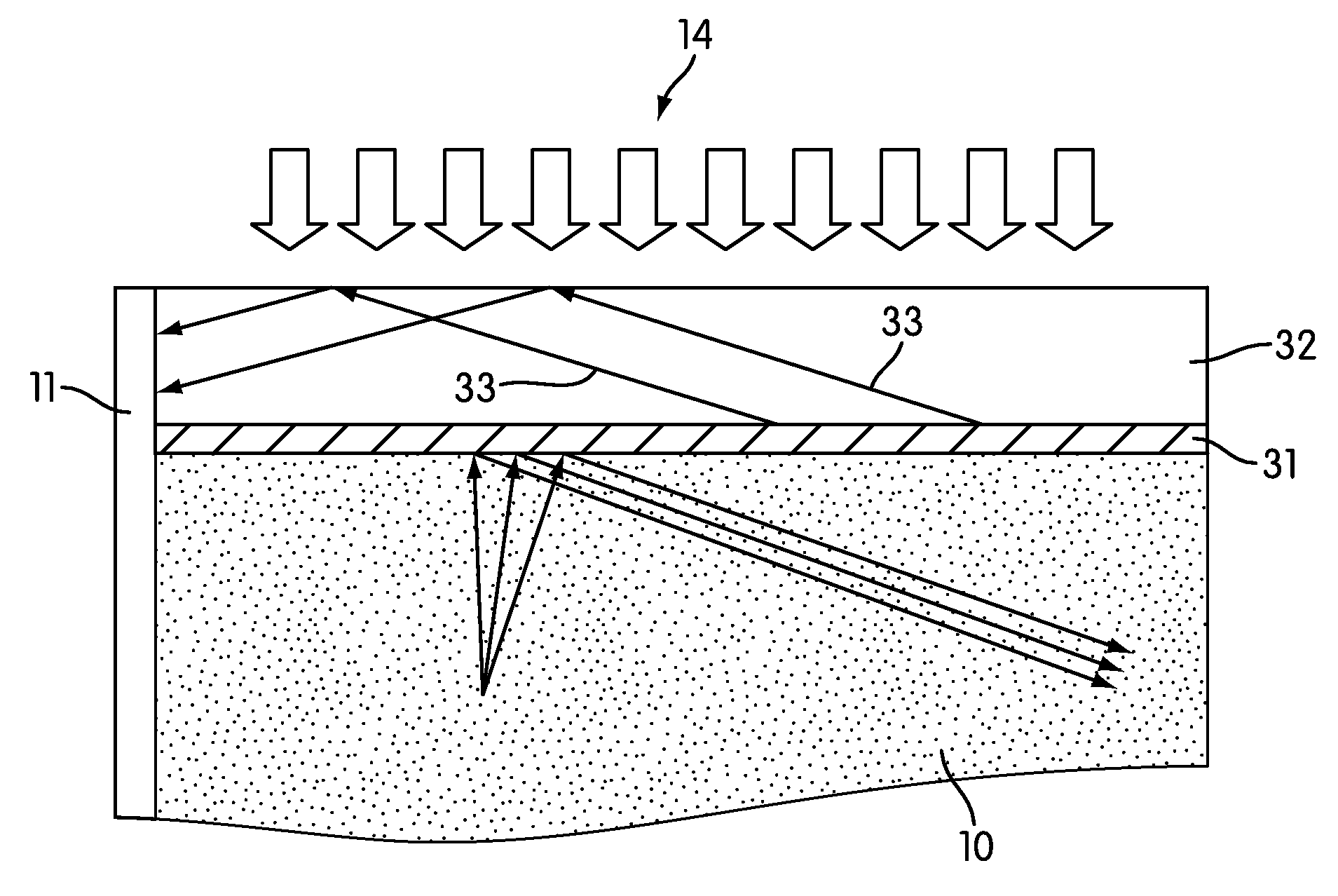
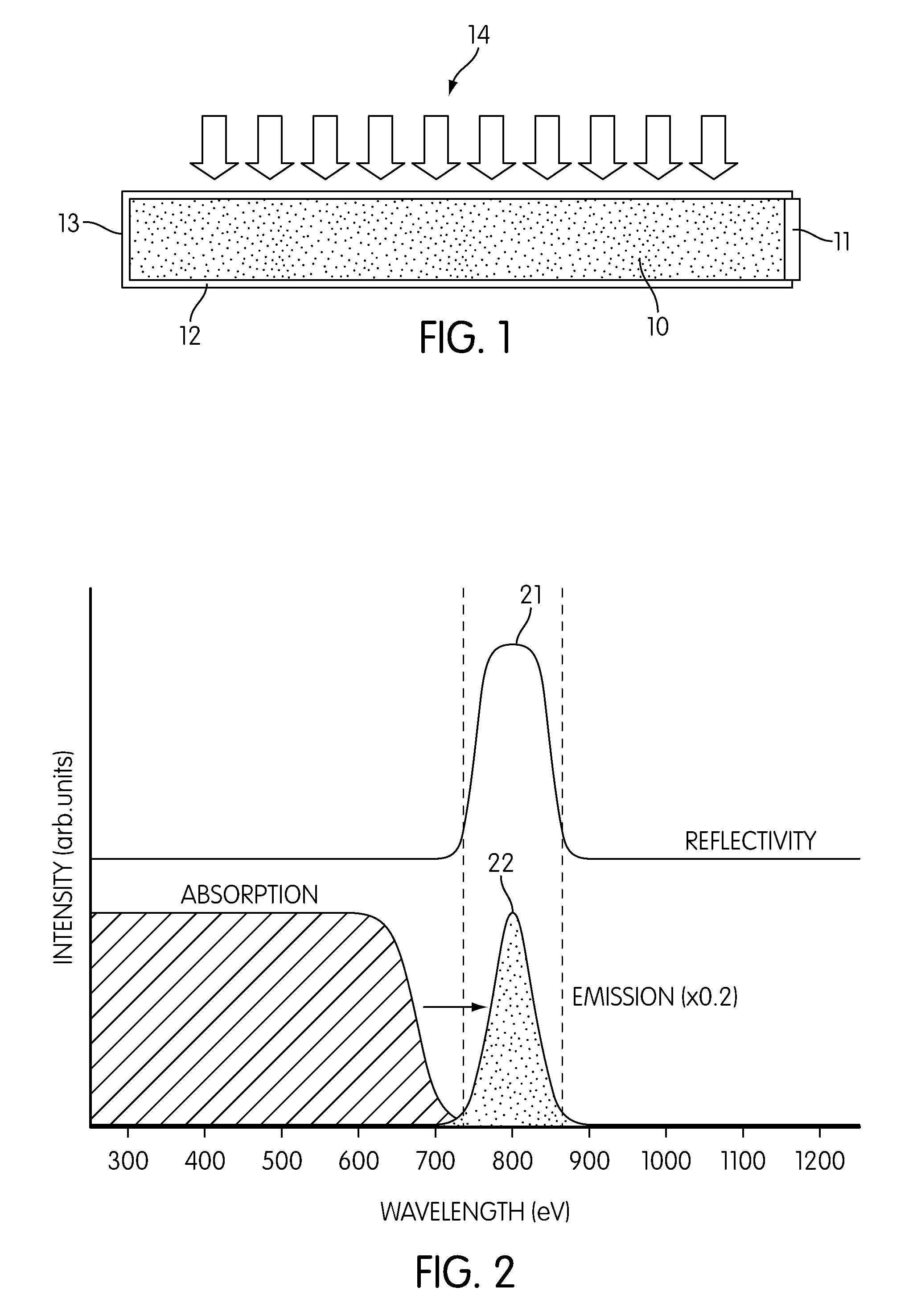
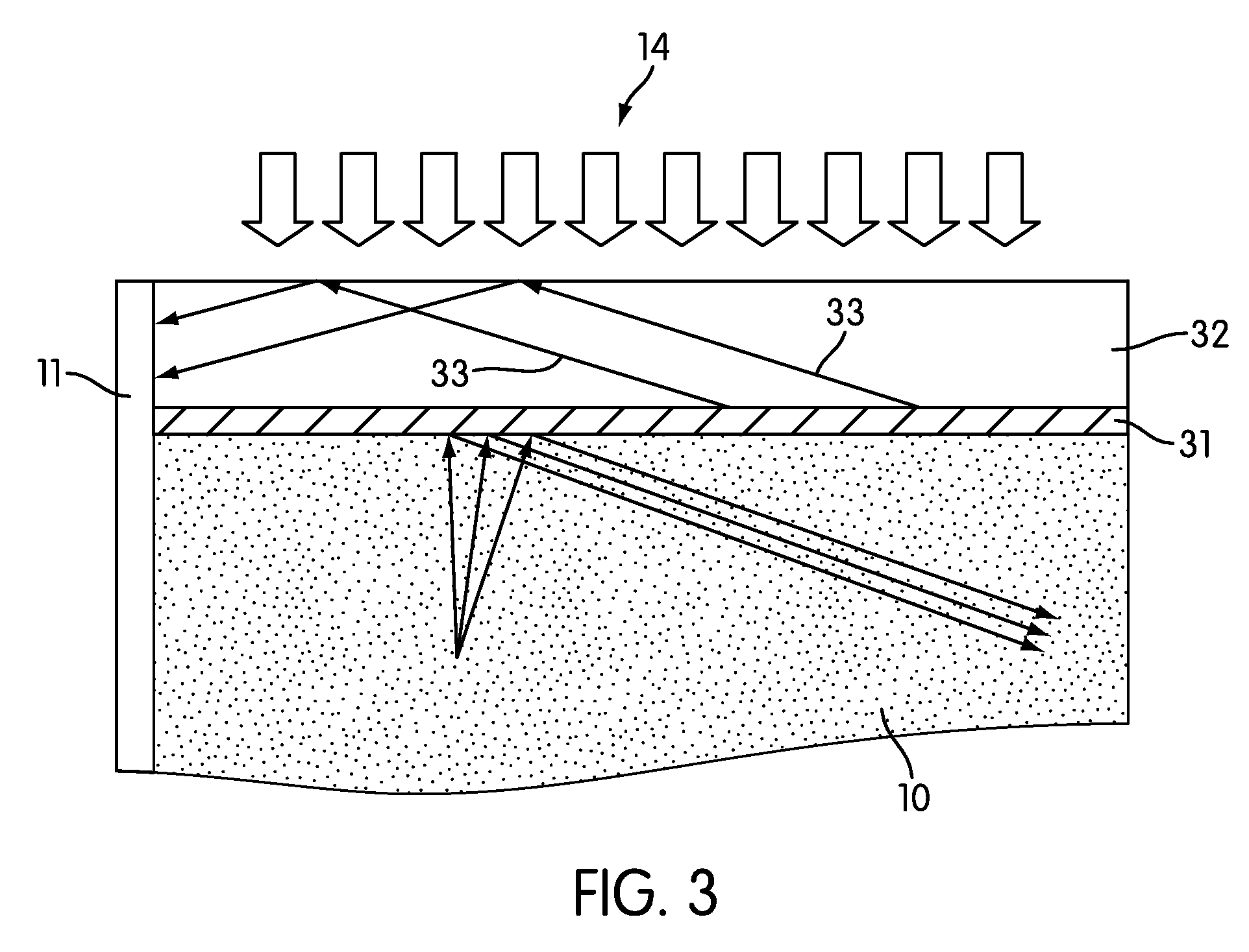
[0019]Disclosed herein are systems and methods for improving luminescent contractor performance. Referring to FIG. 1, a luminescent concentrator (LC) device may comprise a transparent substrate 10, a photovoltaic (PV) cell 11 attached to one of its side edges (or, in the case of an array of PV cells, to more than one side edge), and a band-blocking reflector 12 which may cover the top and bottom surfaces of the transparent substrate 10, as well as the side edge(s) 13 where no cells have been attached. In this case, the orientation of the LC is such that the “top surface” is that which faces the incident solar radiation. The coverage on the opposite surface (or “bottom” surface) and the side edges may be replaced by a mirrored coating.

[0020]The transparent substrate 10 may be made of optically clear matrix such as but not limited to glass or plastic, the matrix containing one or more luminescent materials. When sunlight 14 is incident on the top of the substrate, properly selected lu...


PUM


Abstract

Disclosed herein are systems and methods for improving the performance of a luminescent concentrator. Performance may be enhanced by incorporating a reflector capable of blocking re-emitted photons from the luminescent material used to make frequency down conversion with a narrow reflection band, while allowing broad transmission of incident sunlight. The reflection band of the reflector that spectrally matches to the bandwidth of re-emission from the luminescent material acts as a luminescence cavity to prevent the outgoing re-emission that cannot be waveguided by total internal reflection to the photovoltaic device(s) located at the side edges of the concentrator. Further embodiments include using inorganic phosphors specifically as luminescent materials

Description

REFERENCE TO RELATED APPLICATIONS[0001]This application claims benefit of U.S. Patent Application No. 60 / 853,369, filed Oct. 19, 2006, titled “Methods for performance improvement of luminescent concentrator.” U.S. Patent Application No. 60 / 853,369 is incorporated herein in its entirety.BACKGROUND OF THE INVENTION[0002]1. Field of the Invention[0003]Embodiments of the present invention are directed to the field of photovoltaics (PV), a technology that converts solar energy directly into electrical energy. The field of the invention is specifically directed to a luminescent concentrator device that converts solar energy into electricity.[0004]2. Description of the Related Art[0005]The concept of a luminescent concentrator (LC) for solar energy conversion was introduced in the 1970s to overcome the spectral loss of various solar cells. Spectral loss, in general, is a phenomenon where the shorter the wavelength of the incident light, the lower photocurrent generated in the solar cell. T...

Claims


Application Information

Patent Timeline
IPC IPC(8): H01L31/0232G02F1/35
CPCH01L31/02322H01L31/0547Y02E10/52H01L31/055
Inventor XIANG, XIAO-DONGSHAN, WEI
Owner INTEMATIX
Why Eureka
Try Eureka