Method and System for Increasing Recovery and Preventing Precipitation Fouling in Pressure-Driven Membrane Processes

a technology of precipitation fouling and membrane process, applied in the field of methods and, can solve the problems of membrane fouling, less effective, membrane fouling, etc., and achieve the effect of easy estimation of the induction tim

Active Publication Date: 2008-09-25
BEN GURION UNIVERSITY OF THE NEGEV
View PDF15 Cites 22 Cited by
  • Summary
  • Abstract
  • Description
  • Claims
  • Application Information

AI Technical Summary

Benefits of technology

[0040]Having obtained and or experimentally determined the values of A, B and S, for the relevant salt and system, one may easily estimate the induction time, τ. The periodic reversal will then be set to take place at some time less than

Problems solved by technology

During the filtration process the membranes become fouled and as a result less effective.
Membrane fouling has become one of the primary impediments to their acceptance in water treatment applications.
The occurrence of membrane fouling in reverse osmosis and nanofiltration processes leads to reduction in the production rate and sometimes to loss of solute rejection.
These saturation limits can be moderately increased by feeding antiscalants to the membrane feed end which increase chemical pretreatment costs.
These conflicting requirements make design of new water treatment plants quite difficult, which resulted in various new strategies that have been proposed (for conventional ways of dealing with this see e.g., “Innovative System Designs to Optimize Performance of Ultra-low Pressure Reverse Osmosis Membranes”, Nemeth, J., Desalination, 118, 63-71, 1998).
However none of these publications teach or propose a solution for preventing precipitation fouling.
This last method reduces th

Method used


Image

  • Method and System for Increasing Recovery and Preventing Precipitation Fouling in Pressure-Driven Membrane Processes
  • Method and System for Increasing Recovery and Preventing Precipitation Fouling in Pressure-Driven Membrane Processes
  • Method and System for Increasing Recovery and Preventing Precipitation Fouling in Pressure-Driven Membrane Processes

Examples


example 1

[0095]This is a calculation example comparing performance of an RO unit desalting brackish water with calcium sulfate fouling potential using a standard tapered flow design and the example using reverse flow to reduce energy and chemical costs. This example uses the commercial membrane design software, Integrated Membrane Systems, of Hydranautics, Inc, but any standard commercial software could be used to generate the same results. Column 2 of table 2 represents the composition of the brackish water to be treated and is similar in its major ion composition to the water of wells sampled at Mashabe Sadeh in the Israel Negev region. The water composition is detailed in Table 2 here below.

TABLE 2Compositions in RO of Negev region brackish waterConcentrate(80%RawFeedrecovery)SpeciesCa+2206206973Mg+27272402Na+6246242632K+17.517.578NH4+0.30.31.3CO3−20.300HCO3−324115.3353SO4−2420586.52714Cl−103010304802SiO217.517.574GeneralPropertiespH7.466.7Temp. ° C.252525TDS2711.6267212042Conductivity471...

example 2

Measuring Calcium Sulfate Induction Times on Pilot RO Unit

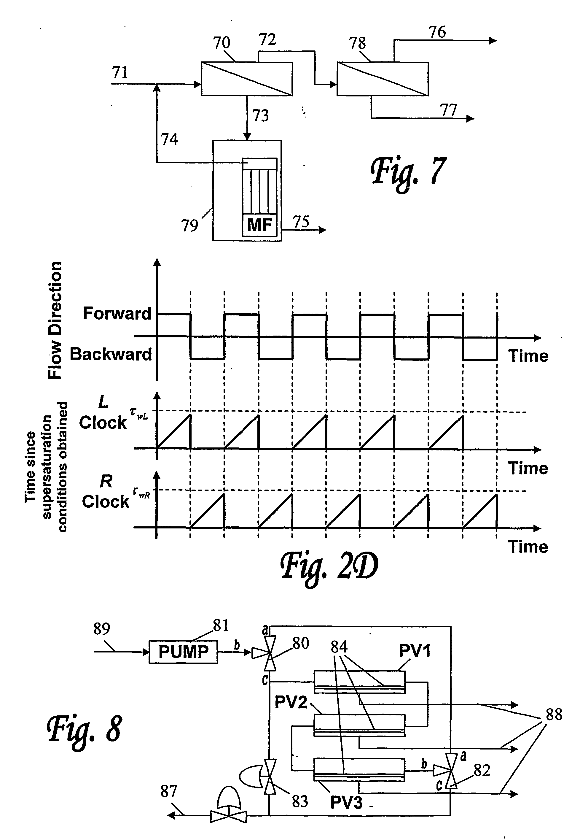
[0098]A block diagram of the test unit that was used in this example is shown in FIG. 8. As shown in FIG. 8, three PVs, PV1, PV2 and PV3, were connected in series each containing 2 spiral wound elements 84 of ESPAL low pressure membrane from Hydranautics Inc. with 2.5 inch diameter and 40 inch length for a total of 6 elements in series (6×2.6 15.6 m2 total membrane area). The feed tank (not shown) was filled with 100 L of a solution of sodium sulfate to which an equimolar solution of calcium chloride was added. Two levels of feed solutions (89) were used: (i) 7.5 mM calcium sulfate (with 15 mM NaCl); and (ii) 10 mM calcium sulfate (with 20 mM NaCl). These feed solutions (89) were under-saturated with respect to calcium sulfate dihydrate. The saturation index for 7.5 mM solution was 0.32 and that for 10 mM calcium sulfate was 0.46. In order to generate super-saturation, the pressures were adjusted so that 65-82% of the feed fl...

example 3

[0111]The following synthetic solution was prepared to simulate a potentially scaling feed:

[0112]CaCl2: 2.5 mmol / L

[0113]NaHCO3: 5 mmol / L

[0114]NaCl: 5 mmol / L

in a volume of 150 L. The pH was adjusted to pH 7.2 with HCl requiring 16.7 mg / L. This solution has a calculated LSI of 0.04 (equivalent to a super-saturation ratio of 100.04=1.1). The calcium ion concentration for this solution will be 100 mg / L.

[0115]This solution is fed to the reverse flow unit shown in FIG. 8 at a flow rate of 1000 L / min and 700 L / min of permeate were removed through the RO membranes 84. This unit contains three pressure vessels in series, PV1, PV2 and PV3, each of which comprises two ESPA 2540 (2.5 in diameter, 40 inch long) spiral wound low pressure RO elements, wherein the membrane area of each membrane element is about 2.6 m2. This results in an average flux of 45 L / m2-h. The permeate flow 88 and concentrate flow 87 are returned to the feed tank (not shown) so that the composition of the feed flow 89 remai...


PUM

PropertyMeasurementUnit
Diameteraaaaaaaaaa
Timeaaaaaaaaaa
Pressureaaaaaaaaaa

Abstract

The invention provides a process for purifying water containing soluble species capable of forming one or more sparingly soluble salts or minerals, said process comprising feeding a pressurized water stream into a treatment zone having one or more membranes disposed therein, passing said stream along said membrane(s) to recover a permeate and to withdraw a concentrate therefrom while periodically reversing the direction of the flow of said stream in said treatment zone, wherein the periodicity of the flow reversal is such that said one or more membranes are exposed to supersaturation conditions evolving in said water stream for a period of time which is less then the time required for said supersaturated water stream to precipitate one or more of said sparingly soluble salts and/or minerals therefrom.

Description

FIELD OF THE INVENTION[0001]The present invention generally relates to improving the recovery, and to prevention of precipitation fouling, in liquid filtration processes. More particularly, the invention relates to a method and system for preventing precipitation fouling in reverse osmosis and nanofiltration pressure-driven filtration processes, and for increasing recovery by precipitation of supersaturated minerals from the concentrate stream prior to its further desalination.BACKGROUND OF THE INVENTION[0002]Membrane filtration processes provide attractive solutions for various water treatment applications such as used for the removal of inorganic constituents and in particular in desalting brackish water and seawater and for the removal of Synthetic Organic Chemicals (SOC). Since traditional water treatment methods are not always able to meet the requirements imposed by the drinking water regulations, membrane filtration processes are becoming preferable in such applications, part...

Claims


Application Information

Patent Timeline
IPC IPC(8): B01D61/02B01D35/157B01D61/10B01D61/12B01D61/58B01D65/08C02F1/44
CPCB01D61/02B01D61/025B01D61/027B01D61/10B01D61/12C02F1/441B01D61/364B01D61/422B01D61/58B01D65/08B01D2321/2083B01D61/147
Inventor GILRON, JACKKORIN, ELIYAHU
Owner BEN GURION UNIVERSITY OF THE NEGEV
Why Eureka
Try Eureka