
Polymer Thin Film, Patterned Substrate, Patterned Medium for Magnetic Recording, and Method of Manufacturing these Articles

Active Publication Date: 2008-09-25
HITACHI LTD
View PDF6 Cites 43 Cited by
  • Summary
  • Abstract
  • Description
  • Claims
  • Application Information

AI Technical Summary

Benefits of technology

[0028]With a configuration as described above, the cylindrical phases are oriented in the pass-through direction of the polymer thin film, which otherwise tend to be oriented parallel therein

Problems solved by technology

As a pattern becomes minuter, the top-down technique has more difficulty in terms of an equipment and a process for manufacturing a minute pattern.
In particular, if a minute pattern is processed in a several tens nanometers scale or less, the pattern has to be processed using an electron beam or deep ultraviolet rays, which requires an equipment with a large amount of investment.
Further, if a pattern is too minute to make it impossible to be created using a mask, a direct writing technique has to be used, which significantly reduces a process throughput.
However, the first conventional technique has a problem that, in order to apply the extremely high electric field to the film composed of block copolymers, voltage has to be applied to an extremely narrow gap between a surface of the film and an electrode which are closely contacted with each other.
The second conventional technique has a problem that it is not generally easy to treat the surface of the substrate such that the surface has an equal affinity for each block chain of the block copolymers.
The third conventional technique has a problem that the film is required to have a gradual change in its thickness, which makes it impossible to obtain a substrate having a structure in which the cylindrical phases are uniformly provided over and perpendicular to the substrate.
The conventional techniques above are thus not suitable for providing a structure in which the cylindrical phases are oriented perpendicular to a substrate.
However, the techniques have a difficulty in obtaining the structure having the cylindrical phases perpendicular to a substrate.
The fourth conventional technique has a problem that a periodic array pattern of the cylindrical phases distributed in the continuous phase can be obtained only in a limited portion of the polymer thin film.

Method used


Image

  • Polymer Thin Film, Patterned Substrate, Patterned Medium for Magnetic Recording, and Method of Manufacturing these Articles
  • Polymer Thin Film, Patterned Substrate, Patterned Medium for Magnetic Recording, and Method of Manufacturing these Articles
  • Polymer Thin Film, Patterned Substrate, Patterned Medium for Magnetic Recording, and Method of Manufacturing these Articles

Examples


example 1

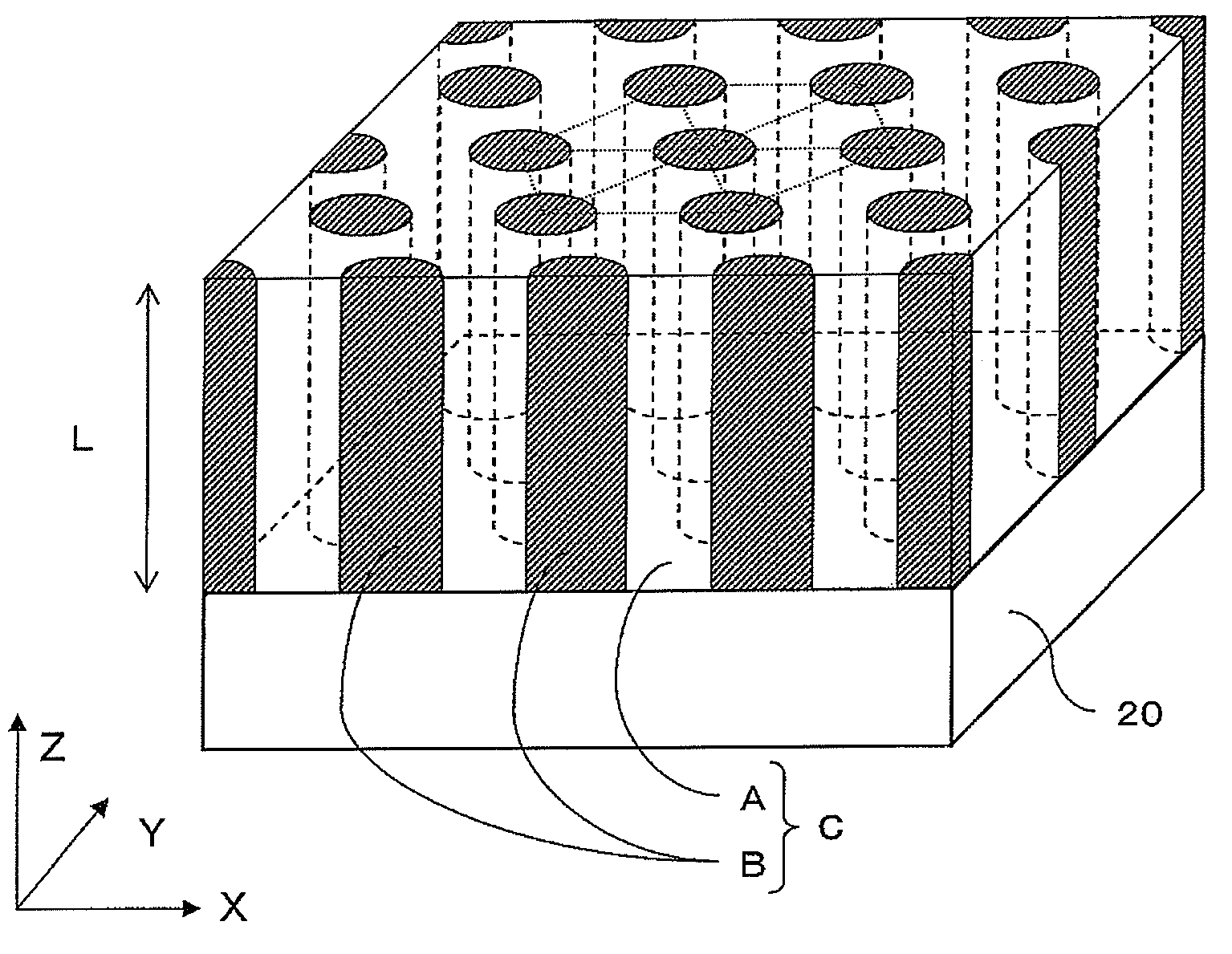
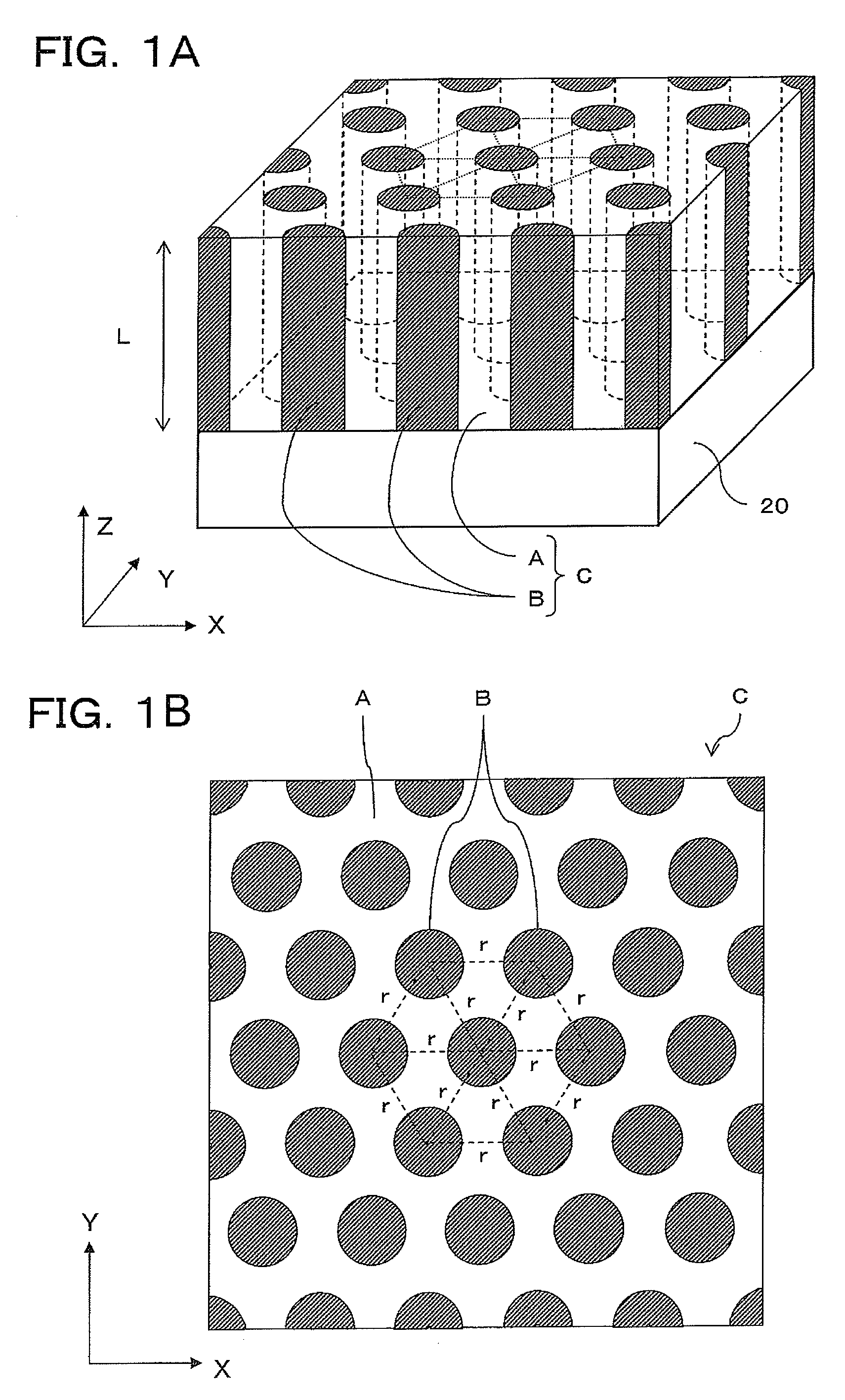
[0136]In Example 1, the polymer thin film C having a structure in which the cylindrical phases B made of a polymethylmethacrylate (PMMA) were arrayed in the continuous phase A made of a polystyrene (PS), was formed on the substrate 20 (see FIG. 1A and FIG. 1B).

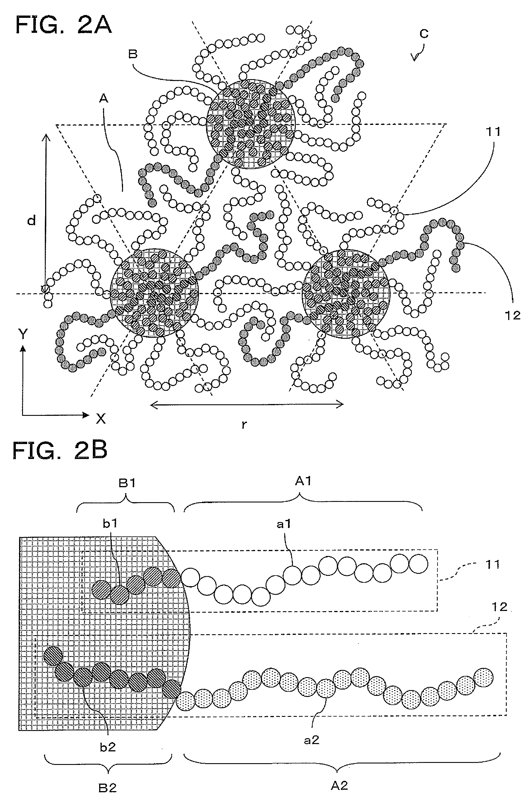
[0137]The first and second block copolymers 11,12 (see FIG. 2B as needed) constituted a mixed system composed of two types of diblock copolymers (PS-b-PMMA). The two PS-b-PMMAs were both composed of PS and PMMA as monomers having different molecular weights.

[0138]More specifically, a first PS-b-PMMA had number average molecular weights Mn of the PS block chains and the PMMA block chains of 35,500 and 12,200, respectively. A molecular weight distribution of the entire first PS-b-PMMA Mw / Mn was 1.04.

[0139]A second PS-b-PMMA had the number average molecular weights Mn of the PS block chains and the PMMA block chains of 46,000 and 21,000, respectively. The molecular weight distribution Mw / Mn of the entire second PS-b-PMMA was 1.09...

example 2

[0174]Example 2 was conducted to examine an effect of a mixed ratio volume (fraction) of the first PS-b-PMMA and the second PS-b-PMMA, in forming, on the substrate 20, the polymer thin film C in which the cylindrical phases B composed of PMMA were periodically arrayed in the continuous phase A composed of PS.

[0175]Example 2 used a mixed system of two block copolymers same as that in Example 1. That is, the first PS-b-PMMA had the number average molecular weights Mn of the PS block chains and the PMMA block chains of 35,500 and 12,200, respectively. The molecular weight distribution Mw / Mn of the first PS-b-PMMA was 1.04. The second PS-b-PMMA had the number average molecular weights Mn of the PS block chains and the PMMA block chains of 46,000 and 21,000, respectively. The molecular weight distribution Mw / Mn of the second PS-b-PMMA was 1.09.

[0176]The mixed system had a ratio of the number average molecular weight Mn of the PS block chains of the first PS-b-PMMA as the primary componen...

example 3

[0181]Example 3 was conducted to examine an effect of a ratio of molecular weights of the first PS-b-PMMA and the second PS-b-PMMA, in forming, on the substrate 20, the polymer thin film C in which the cylindrical phases B composed of PMMA were periodically arrayed in the continuous phase A composed of PS.

[0182]Example 3 also used a mixed system of two block copolymers. The first PS-b-PMMA as the primary component is same as that used in Example 1, and had number average molecular weights Mn of the PS block chains and the PMMA block chains of 35,500 and 12,200, respectively. The molecular weight distribution Mw / Mn of the first PS-b-PMMA was 1.04. A plurality of the second PS-b-PMMAs were used as the secondary component used having following various number average molecular weights Mn of the PS block chain and the PMMA block chain, as indicated in parentheses: PS(260,000)-b-PMMA(63,500), PS(140,000)-b-PMMA(60,000), PS(52,000)-b-PMMA(52,000), PS(46,000)-b-PMMA(21,200), and PS(12,800)-...


PUM

PropertyMeasurementUnit
Fractionaaaaaaaaaa
Fractionaaaaaaaaaa
Weightaaaaaaaaaa

Abstract

A polymer thin film in which cylindrical phases are distributed in a continuous phase and are oriented in a pass-through-direction of the film includes at least: a first block copolymer including at least a block chain A1, as a component of the continuous phase, composed of polymerized monomers a1, and a block chain B1, as a component of the cylindrical phases, composed of polymerized monomers b1; and a second block copolymer including at least a block chain A2, as a component of the continuous phase, composed of polymerized monomers a2, and a block chain B2, as a component of the cylindrical phases, composed of polymerized monomers b2, with the second copolymer having a degree of polymerization different from that of the first copolymer. A film thickness of the polymer thin film and an average center distance between adjacent cylindrical phases have a relation represented by a predetermined expression.

Description

CROSS REFERENCE TO RELATED APPLICATIONS[0001]This application claims the benefit of Japanese Patent Application No. 2007-072344 filed on Mar. 20, 2007, the disclosure of which is incorporated herein by reference.BACKGROUND OF THE INVENTION[0002]1. Field of the Invention[0003]The present invention relates to a polymer thin film having a microphase-separated structure in which cylindrical phases (a cylindrical microdomain) distributed in a continuous phase are oriented in a pass-through direction of the polymer thin film and provided in a substantially periodic array pattern, and a method of manufacturing the same. The present invention also relates to a patterned substrate having on its surface the periodic array pattern of the microphase-separated structure, and a method of manufacturing the same. The present invention also relates to a patterned medium for magnetic recording manufactured by using the patterned substrate, and a method of manufacturing the same.[0004]2. Description o...

Claims


Application Information

Patent Timeline
IPC IPC(8): G11B5/73B05D3/02B44C1/22
CPCB05D1/34B05D3/0254Y10T428/269B05D5/00G11B5/855B05D3/0493G03F7/0002
Inventor HASEGAWA, HIROKAZUTAKENAKA, MIKIHITOCHEN, FENGYOSHIDA, HIROSHI
Owner HITACHI LTD
Learn More