Stage Apparatus and Exposing Apparatus

a technology of stage apparatus and exposing apparatus, which is applied in the direction of mechanical conveyors, instruments, photomechanical treatment, etc., can solve the problems of high constraint of a structure of the z leveling mechanism, difficult to reduce the movable stage, and high cost of producing apparatus, so as to reduce the weight of the movable section, reduce the influence of vibration, and reduce the production cost

Inactive Publication Date: 2008-10-02
NIKON CORP
View PDF7 Cites 31 Cited by
  • Summary
  • Abstract
  • Description
  • Claims
  • Application Information

AI Technical Summary

Benefits of technology

[0049]The stage apparatus of the present invention includes a flexible structure or a movable mass body. The movable section can be reduced in weight or influence of vibration can be reduced. Therefore, according to the exposing apparatus of the present invention, the producing cost can be reduced, the vibration isolation performance can be enhanced, and the apparatus performance (exposing precision or the like) can be enhanced.
[0050]According to the first, second and fifth stage apparatuses of the present invention, since the rigid structure and the flexible structure can be combined, the movable section can be reduced in size and weight, vibration caused when the movable section is driven is not easily transmitted to

Problems solved by technology

Therefore, it was difficult to reduce the movable stage including expensive member having high rigidity in size and weight, the producing cost of the exposing apparatus was high, and in order to enhance the driving speed of the movable stage, it was necessary to increase the output of the driving device.
When the movable stage was driven along the guide member, vibration generated in the driving device was easily transferred to the wafer,

Method used


Image

  • Stage Apparatus and Exposing Apparatus
  • Stage Apparatus and Exposing Apparatus
  • Stage Apparatus and Exposing Apparatus

Examples


first embodiment

[0076]Preferred embodiments of the present invention will be explained with reference to FIGS. 1 to 15. In the embodiments, the invention is applied to a full field exposing type projection exposing apparatus such as a stepper, and to a scanning exposing type projection exposing apparatus like a scanning stepper.

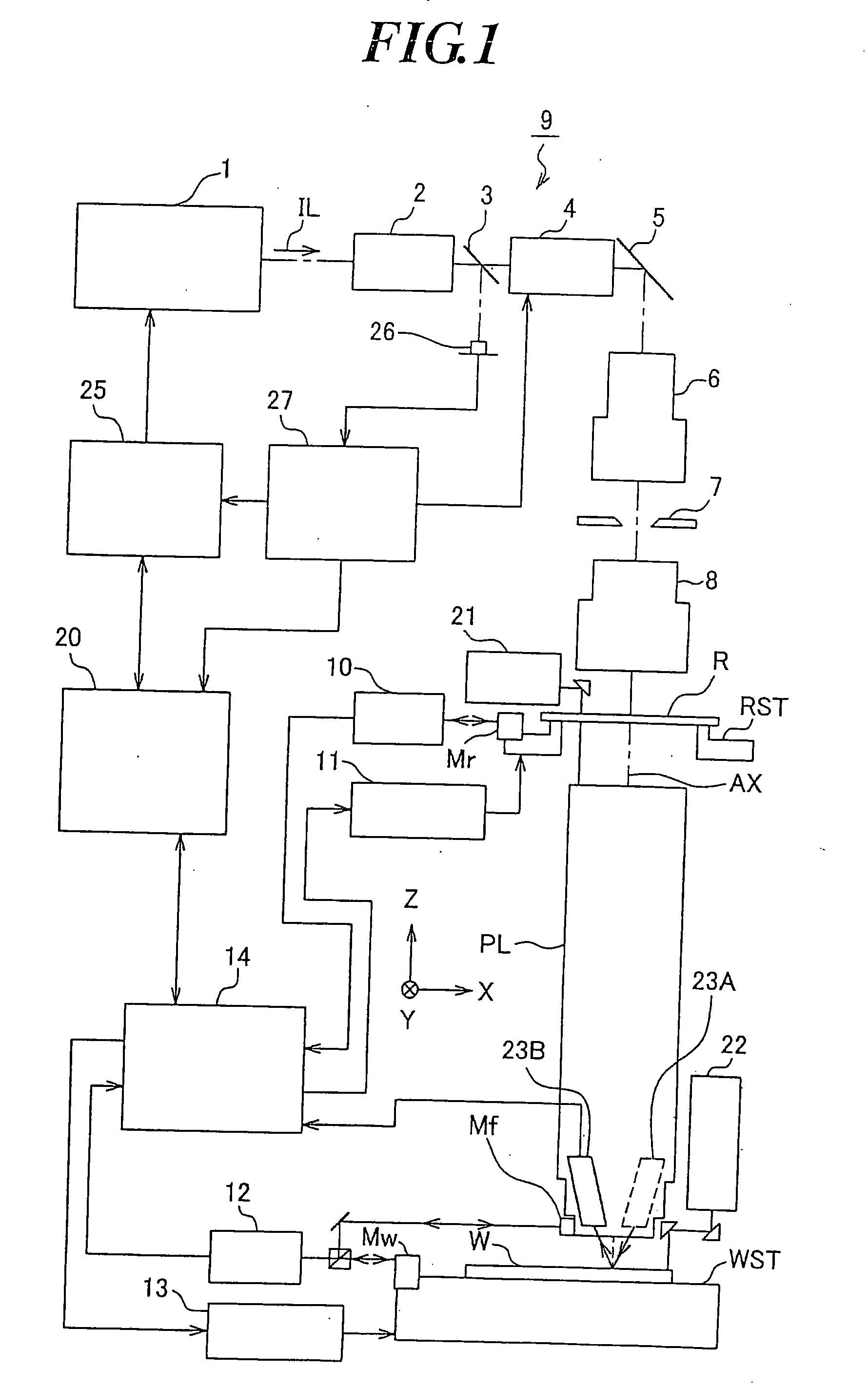
[0077]FIG. 1 is a block diagram of function units constituting a projection exposing apparatus as an exposing apparatus of the embodiment. In FIG. 1, a chamber for accommodating the projection exposing apparatus is omitted. In FIG. 1, a laser light source 1 including a KrF excimer laser (wavelength: 248 nm) or an ArF excimer laser (wavelength: 193 nm) is used as an exposing light source. It is also possible to use, as the exposing light source, a light source which emits laser light in ultraviolet region in lasing stage such as an F2 laser (wavelength: 157 nm), a light source which emits high harmonic laser light in vacuum ultraviolet region obtained by converting laser ligh...

second embodiment

[0139]Next, a second embodiment of the invention will be explained with reference to FIGS. 16 and 17. A projection exposing apparatus of the second embodiment corresponds to the projection exposing apparatus shown in FIGS. 1 and 2 to which a mechanism for diagnosing or monitoring the state of the projection optical system PL is added. In FIGS. 16 and 17, portions corresponding to FIGS. 1, 2 and 8 are designated with the same symbols, and detailed explanation thereof will be omitted.

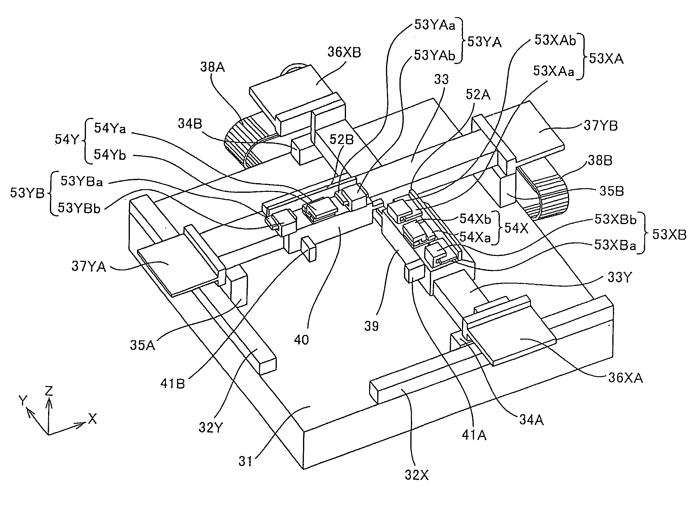
[0140]FIG. 16A is a schematic plan view showing a wafer stage system of the projection exposing apparatus of the embodiment. In FIG. 16A, the Y-axis guide 33Y and the X-axis guide 33X (guide members) are disposed such that they intersect with each other at right angles. The Y-axis slider 39 and the X-axis slider 40 (sliders) are connected to each other via a connecting member (not shown) such that they can move along the Y-axis guide 33Y and the X-axis guide 33X. The wafer stage WST which holds the wafer ...

third embodiment

[0146]Next, a third embodiment of the invention will be explained with reference to FIG. 18. A projection exposing apparatus of this embodiment includes a filtered reaction mass type vibration attenuation mechanism like the first embodiment. In FIG. 18, portions corresponding to FIG. 2 are designated with the same symbols, and detailed explanation thereof will be omitted.

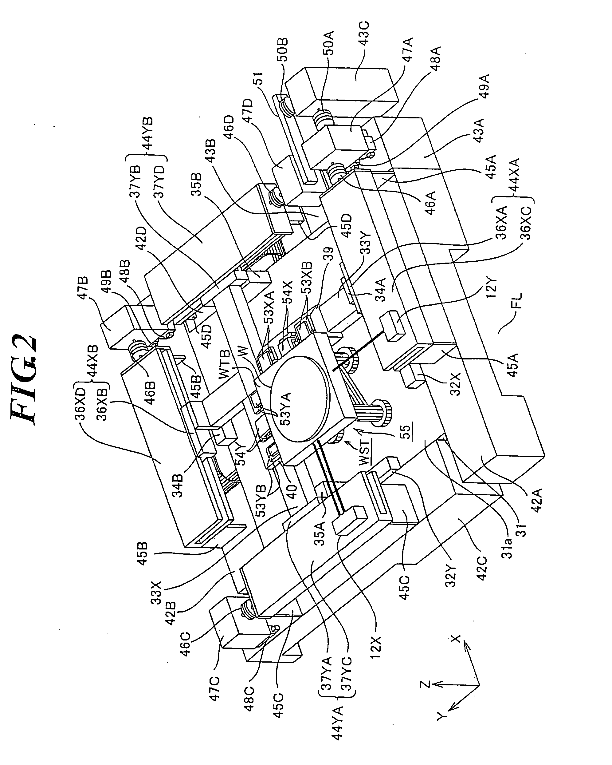
[0147]FIG. 18 is a schematic view of a structure of the wafer stage system of the projection exposing apparatus. In FIG. 18, base members 42A and 42B are disposed on the floor FL (disposing surface) such as to sandwich the wafer base 31 in the Y direction. In this embodiment also, the wafer base 31 and the base members 42A and 42B may be integrally formed together. A Y-axis guide 33YA having a stator of a linear motor is disposed above a guide surface 31a of the wafer base 31 substantially in parallel to the Y-axis. A Z leveling mechanism 55A is disposed such that the Z leveling mechanism 55A can move in the Y direc...


PUM


Abstract

Disclosed is a stage apparatus which drives an object, comprising a base member, a first guide member disposed along a guide face of the base member, a second guide member disposed along the guide face so as to intersect with the first guide member, first and second sliders disposed such that the first and second sliders can move along the first and the second guide members, respectively, a connecting member having a flexible structure to connect the first and the second sliders to each other, and a movable stage which is to hold the object and is movably disposed on the guide face, and which is connected to the first and the second sliders.

Description

BACKGROUND OF THE INVENTION[0001]1. Field of the Invention[0002]The present invention relates to a stage apparatus for driving an object. Further, the present invention also relates to an exposing apparatus used for transferring a predetermined pattern onto a substrate when various devices such as a semiconductor device and a liquid crystal display are produced.[0003]2. Description of the Related Art[0004]In a lithography step which is one of producing steps of a semiconductor device, an exposing apparatus is used for transferring a pattern formed on a reticle (or photomask) as a mask on a wafer (such as a glass plate) as a substrate on which a photoresist is applied, and for exposing the pattern. As the exposing apparatus, a full field exposing type (static exposing type) projection exposing apparatus like a stepper, or a scanning exposing type projection exposing apparatus (scanning type exposing apparatus) like a scanning stepper is used.[0005]In such exposing apparatuses, a stru...

Claims


Application Information

Patent Timeline
IPC IPC(8): H01L21/677
CPCG03F7/70716G03F7/709
Inventor EBIHARA, AKIMITSU
Owner NIKON CORP
Why Eureka
Try Eureka