[0013]The present invention may have the
advantage over the related art in that the dynamic
internal resistance of the current-limiting device drops with increasing charging state, i.e., the first potential of the energy storage device, while allowing a constant
high current to flow. Thus, a significant
power loss in the current-limiting device occurs only at the beginning of the charging process of the energy storage device. At the same time, the active current-limiting device prevents a higher current than the predefined maximum current from flowing during the initial charging of the energy storage device. The efficiency of the
voltage transformer is very high because no resistors need to be connected downstream from it in the main current path. In addition, the number of discrete components for the device needed for charging is reduced to the active current-limiting device and the switched voltage transformer device, which may also be integrated together in a housing, as well as an additional
inductance and an external
diode.
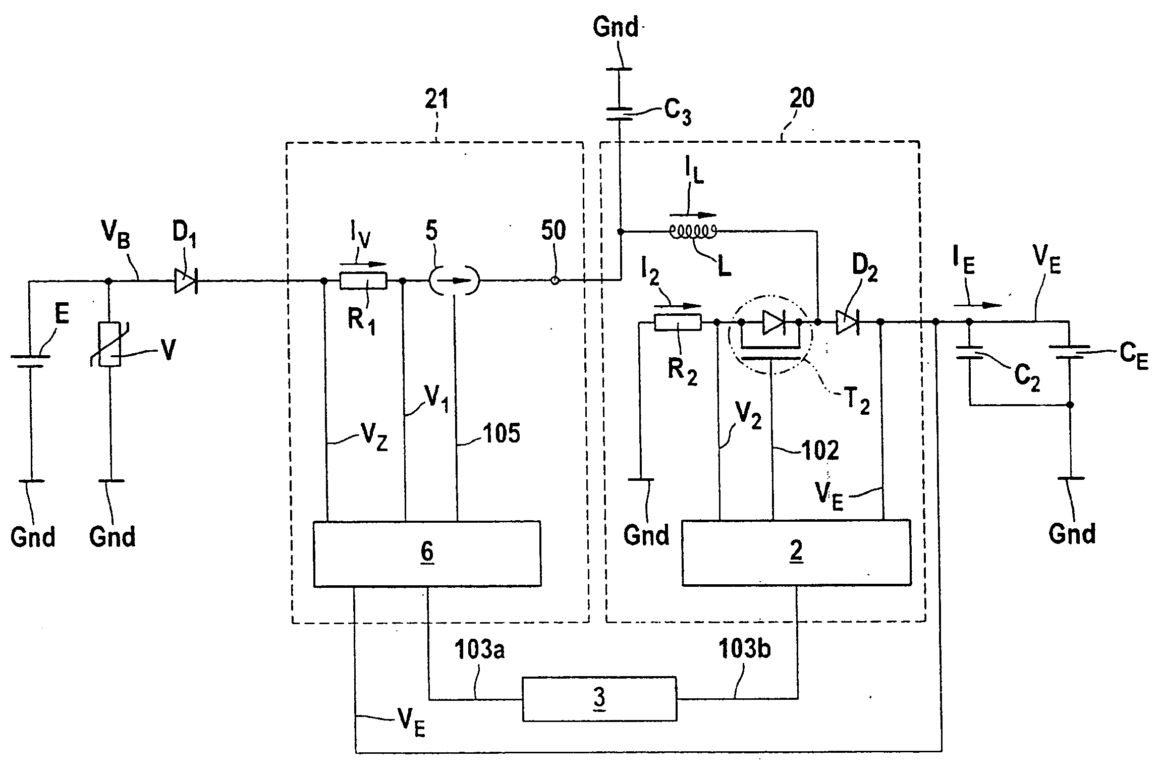
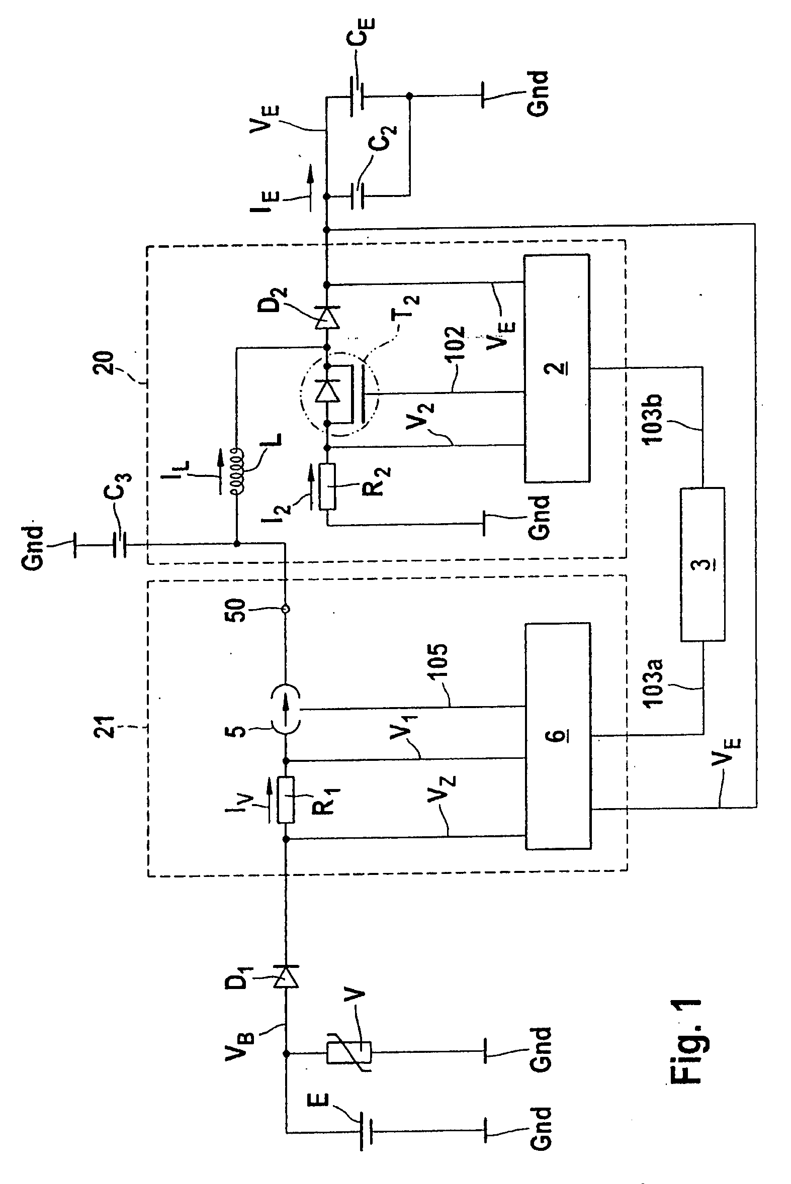
[0015]According to another particularly preferred refinement of the present invention, the current-limiting device has a first switching element, which is situated in the main current path and has a
control unit which detects the
supply current and generates a
control signal which switches the first switching element to the non-conductive state when the supply current exceeds a predefined maximum current and switches the first switching element to the conducting state when the supply current is less than the predefined minimum current and / or switches to the conductive state after a predefined time period. In addition, the device has a freewheeling device which connects a tie point of the main current path between the current-limiting device and the voltage transformer device to a ground of the electrical power source. This device has the
advantage that almost no power is dissipated in the current-limiting device because in the non-conducting state of the switching element no supply current flows, while in the conducting state the resistance of the switching element is negligibly low. This device therefore warms up advantageously only to a very small degree.
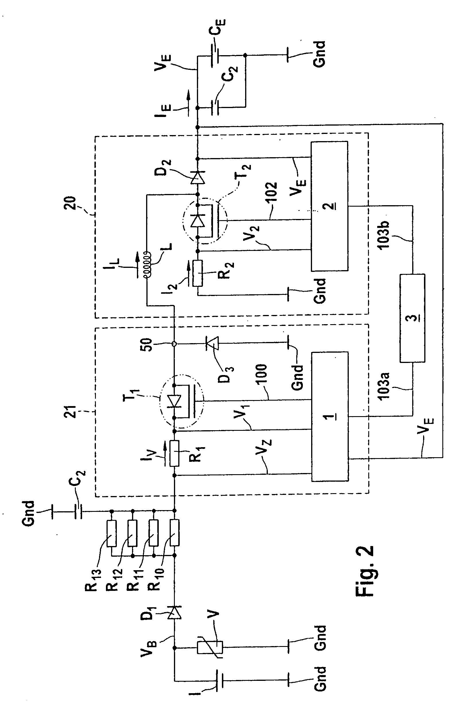
[0016]According to another refinement of the present invention, the freewheeling device has a
diode which connects the main current path to the ground in the reverse direction. According to a preferred refinement, the freewheeling device has a third switching device, which is connected in phase opposition to the first switching element by the
control unit. This reduces the
power loss in the device by the amount that would be dissipated in the freewheeling
diode in the above-mentioned refinement.
[0017]According to a further, particularly preferred, refinement of the present invention, the
control unit detects the first potential of the energy storage device and / or the electrical supply potential. The control unit sets the predefined maximum current to a first maximum current when the first potential is below a first threshold value and to a second maximum current when the first potential is above the first threshold value. The first maximum current may be lower than the second maximum current. In addition, the second maximum current may be selected to be so high that the supply current is not limited by the current-limiting device. The
advantage is in that the current-limiting device no longer limits the supply current in a high charging state of the energy storage device and thus no power is dissipated in the current-limiting device.
[0019]According to another refinement of the present invention, the current-limiting device has a
storage area in which the threshold value, the first and second maximum currents, and / or the minimum current are stored. This makes it possible to adapt the device to given specifications so that the maximum currents are within allowed parameters.
[0022]According to one refinement of the present invention, the current-limiting device has an FET
transistor which is situated in the main current path, the gate and source of the FET
transistor being insulated from each other. In the non-conducting state, the gate is connected to ground, rather than to the source. The potential at the source is thus not determined by the
switching signal. A control unit detects the supply current and generates a
control signal which switches the first switching element into the non-conducting state when the supply current exceeds a certain maximum current and connects the switching element to ground when the supply current is lower than a predetermined minimum current and / or after a predefined time period. The
inductance in the circuit and the non-existent feedback between gate and source of the FET
transistor may cause the potential at the source to drop below the ground potential and thus keep the FET transistor dynamically conducting until the current in the inductive circuit drops to the ground potential. This advantageously allows a freewheeling device to be omitted which is needed to provide a freewheeling current for the
inductance in the event of a blocked first switching device. In addition, a self-regulating switching-off operation results, which prevents the occurrence of
induced voltage peaks.

