Magnetic tunnel junction magnetic memory

a magnetic memory and tunnel junction technology, applied in the field of magnetic tunnel junction magnetic memory, can solve the problems of limited capacity, limit the integration of possible solutions, and the limits of this architecture are clearly apparent, so as to facilitate write address errors and reduce the size of storage cells, the effect of reducing the consequences of this problem

Active Publication Date: 2008-10-09
COMMISSARIAT A LENERGIE ATOMIQUE ET AUX ENERGIES ALTERNATIVES
View PDF8 Cites 78 Cited by
  • Summary
  • Abstract
  • Description
  • Claims
  • Application Information

AI Technical Summary

Benefits of technology

[0021]In other words, this architecture with selection by magnetic field using rows and columns or conductors can easily result in write addressing errors. Given the fact that the distribution function of the reversal fields of the storage cells can be expected to become wider as their size reduces because it is the geometry of the storage cells (shape, irregularity, defect) that dominates the mechanism for reversing the magnetization, this effect is bound to become worse in future-generation products.
[0022]Another drawback of these prior-art memories is the stability of the magnetization of the storage layer with respect to thermal fluctuations as the size of the storage cell decreases. In fact, the energy barrier that must be overcome in order to switch the magnetization of this layer from one orientation to another is proportional to the volume of this layer. As this volume reduces, the height of the barrier then becomes comparable to thermal agitation kBT where kB is Boltzman's constant. Information written in the memory is then no longer preserved. In order to mitigate the consequences of this problem, one is forced to increase the magnetic anisotropy of the storage layer by choosing a more anisotropic material or by accentuating the shape anisotropy of the storage cell, for example if it has an ellipsoidal shape, by increasing its aspect ratio. But doing this increases the field that is required in order to obtain magnetic switching and hence also increases the power consumed in order to generate the field required to obtain magnetic switching. The current in the word and bit lines may even, at a certain stage, exceed the limiting threshold imposed by electromigration in these conductive lines (typically of the order of 2 107 A / cm2).
[0023]According to an enhancement described, for example, in U.S. Pat. No. 6,385,082, a current pulse is sent through the storage cell during the write process by opening transistor (12) in order to induce significant heating of said storage cell. Increasing the temperature of the storage cell produces a reduction in the magnetic write field required. During this phase when the temperature of the addressed cell is significantly higher than that of the other storage cells, current pulses are sent in lines (14, 15) in order to create two orthogonal magnetic fields that make it possible to switch the magnetization of the storage layer of the junction in question. This thermally-assisted write operation makes it possible to improve write selection because only the selected storage cell is heated and the other half-selected storage cells on the same row or the same column remain at ambient temperature. In other words, the enhancement described in this document aims to increase write selectivity by raising the temperature of the addressed junction whilst retaining the basic concept of writing by sending two orthogonal magnetic-field pulses.

Problems solved by technology

Because of its architecture, this technology makes it possible to produce non-volatile memories using technology that is simple but which has a limited capacity.
The fact that the storage cells are connected in series along each line limits possible integration because the signal becomes weaker and weaker as the number of cells increases.
Given the nature of the mechanism for writing the storage cells, the limits of this architecture are clearly apparent.
If the distribution function of the reversal fields for all the storage cells is wide (in fact it is not uniform because of fabrication constraints and inherent statistical fluctuations), the magnetic field at the selected storage cell must exceed the highest reversal field in the statistical distribution with the risk of inadvertently reversing certain storage cells, located on the corresponding row or column, if their reversal field is in the lower part of the distribution and weaker than the magnetic field generated by the row or column alone.
Conversely, if one wants to make sure that no storage cell can be written by one row or column alone, the write current must be limited so that it never exceeds, for these storage cells, the magnetic field that corresponds to the lower part of the distribution with the risk of not writing the selected storage cell at the intersection of said row and column if its reversal field is in the upper part of the distribution.
In other words, this architecture with selection by magnetic field using rows and columns or conductors can easily result in write addressing errors.
Given the fact that the distribution function of the reversal fields of the storage cells can be expected to become wider as their size reduces because it is the geometry of the storage cells (shape, irregularity, defect) that dominates the mechanism for reversing the magnetization, this effect is bound to become worse in future-generation products.
Another drawback of these prior-art memories is the stability of the magnetization of the storage layer with respect to thermal fluctuations as the size of the storage cell decreases.
But doing this increases the field that is required in order to obtain magnetic switching and hence also increases the power consumed in order to generate the field required to obtain magnetic switching.
This results in partial depolarization of the magnetization of the reference layer which may lead to gradual reduction in the magnetoresistance signal of the tunnel junction and, ultimately, read errors.

Method used


Image

  • Magnetic tunnel junction magnetic memory
  • Magnetic tunnel junction magnetic memory
  • Magnetic tunnel junction magnetic memory

Examples


first embodiment

[0081]In a first embodiment described, more particularly, in relation to FIGS. 3 and 4, the stack of the storage cell comprises a tunnel junction with a single insulating barrier that separates the reference and storage layers.

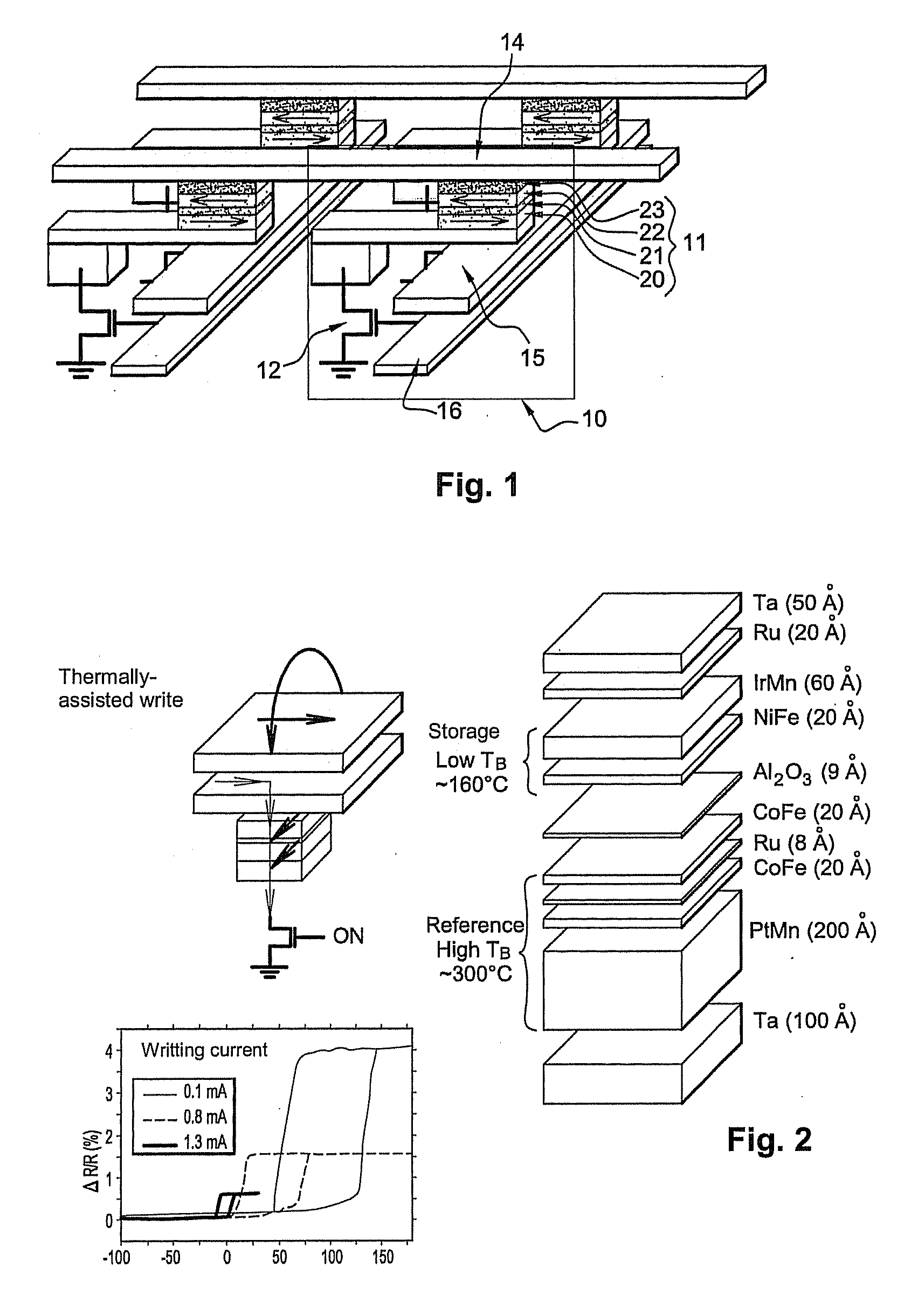
[0082]The storage layer comprises a bilayer that associates a ferromagnetic material with planar magnetization (for example a Permalloy Ni80Fe20 layer having a thickness of the order 1 to 4 nm or a Co90 Fe10 layer having a thickness of 1 to 4 nm) and an antiferromagnetic layer having a moderate blocking temperature, i.e. of the order of 120° C. to 220° C. This blocking temperature must be sufficiently high to ensure that, at standby temperature (not during a write), magnetization of the storage layer is sufficiently pinned to be able to preserve information over a period of several years but not so high as to make it necessary to heat the junction excessively for every write operation because this could cause materials to degrade and power consumption to rise....

second embodiment

[0100]In a second embodiment shown in FIG. 5, the stack consists of a double tunnel-junction structure.

[0101]The storage layer is inserted between the two tunnel barriers with each tunnel barrier having, on the side opposite the storage layer, a reference layer, the magnetization of which is maintained in a fixed direction at the time of a write by magnetostatic interaction with another pinned magnetization layer.

[0102]As in the previous embodiment, here the two reference layers are each separated from the two pinned layers by a thermal barrier, the purpose of which is to confine heat in the central part of the stack at the level where the storage layer is located. These thermal barriers also prevent the pinned layers from being subjected to excessively large temperature fluctuations, thereby avoiding gradual depolarization of their magnetization.

[0103]In this stack, the storage layer advantageously consists of a tri-layer of the CoFe 2 nm / IrMn 5 nm / CoFe 2 nm type comprising a centr...

third embodiment

[0115]In the invention described more particularly in relation to FIG. 6a, the pinned polarizing layer is inserted above the tunnel junction into the conductor which ensures electrical connection to the top of the tunnel junction. Given the greater distance between this polarizing layer and the magnetic storage and reference layers of the tunnel junction compared with the preceding embodiments, flux closure is less satisfactory. Because of this, the field radiated by the polarizing layer acts on the magnetization of the reference layer and also acts significantly on the magnetization of the storage layer. The value of these radiated fields can be calculated by using finite element software such as FLUX3D [CEDRAT: www.cedrat.com]. This value depends on the magnetization of the material of the polarizing layer, its thickness, the width of the conductive line and the distance between said conductive line and the magnetic layers in question.

[0116]The direction of the magnetization of th...


PUM

PropertyMeasurementUnit
thicknessaaaaaaaaaa
thicknessaaaaaaaaaa
thicknessaaaaaaaaaa

Abstract

This magnetic memory with a thermally-assisted write, every storage cell of which consists of at least one magnetic tunnel junction, said tunnel junction comprising at least:
one magnetic reference layer, the magnetization of which is always oriented in the same direction at the time of the read of the storage cell;
one so-called “free” magnetic storage layer, the magnetization direction of which is variable;
one insulating layer sandwiched between the reference layer and the storage layer.
The magnetization direction of the reference layer is polarized in a direction that is substantially always the same at the time of a read due to magnetostatic interaction with another fixed-magnetization layer called the “polarizing layer”.

Description

SUMMARY OF THE INVENTION[0001]The present invention relates to the field of magnetic memories, especially non-volatile random-access magnetic memories used to store and read data in electronic systems. More particularly, it relates to Magnetic Random Access Memories, referred to as M-RAM, based on magnetic tunnel junctions.DESCRIPTION OF THE PRIOR ART[0002]There has been renewed interest in M-RAM memories due to the development of Magnetic Tunnel Junctions (MTJs) which have high magnetoresistance at ambient temperature. These random-access magnetic memories have many significant advantages: speed comparable to that of SRAM (read and write operations last a few nanoseconds),[0003]comparable density to that of DRAM[0004]non volatile like FLASH memory,[0005]no read / write fatigue,[0006]unaffected by ionizing radiation.[0007]This being so, they are increasingly replacing memory that uses more conventional technology based on the charge state of a capacitor (DRAM, SRAM, FLASH) and becomin...

Claims


Application Information

Patent Timeline
Patent Type & Authority Applications(United States)
IPC IPC(8): G11B5/02
CPCG11C11/16H01L27/228H01L43/10Y10S977/933Y10S977/935G11C11/1675H10B61/22H10N50/85H10N50/10
Inventor NOZIERES, JEAN-PIERRESOUSA, RICARDODIENY, BERNARDREDON, OLIVIERPREJBEANU, IOAN LUCIAN
Owner COMMISSARIAT A LENERGIE ATOMIQUE ET AUX ENERGIES ALTERNATIVES
Why Eureka
Try Eureka