Electromagnetic and Thermal Sensors Using Carbon Nanotubes and Methods of Making Same

a technology of carbon nanotubes and electrical and thermal sensors, applied in the field of carbon nanotube fabrics and methods of making same, can solve the problems of high background noise, many ir sensors are expensive, and the detection device is less efficient, so as to reduce the noise 1/f

Active Publication Date: 2008-10-16
NANTERO
View PDF21 Cites 134 Cited by
  • Summary
  • Abstract
  • Description
  • Claims
  • Application Information

AI Technical Summary

Benefits of technology

[0062]Under another aspect of the invention, the region of nanotube fabric may be tun

Problems solved by technology

; however, indirect band gap semiconductors (where an additional phonon energy is required to excite an electron from the valence band to the conduction band, making these detectors less efficient), such as Silicon, are also used as photodetectors.
Since bolometers detect a broad range of radiation above a few microns, bolometers are typically cryogenically cooled to reduce the detection of blackbody radiation that is emitted from the detector material, which leads to a high background noise.
Currently, many IR sensors are expensive, require advanced fabrication techniques that are not compatible with Si—CMOS technology, have limited resolution and do not operate at room temperature (hence require cooling).
The HgCdTe system was plagued by defects, high processing costs, low yields and substantial weight (eliminating crucial man-portable applications).
For VOx microbolometers, increasingly higher resolution IRFPAs are not possible because of limits associated with the TCR of VOx: below 25 microns (required for 640×480 resolution), the TCR of VOx becomes non-linear.
Despite the improvements VOx has contributed to microbolometers, there is evidence that the improvement curve for this material is slowing down and some fundamental limits are preventing the use of t

Method used


Image

  • Electromagnetic and Thermal Sensors Using Carbon Nanotubes and Methods of Making Same
  • Electromagnetic and Thermal Sensors Using Carbon Nanotubes and Methods of Making Same
  • Electromagnetic and Thermal Sensors Using Carbon Nanotubes and Methods of Making Same

Examples


Embodiment Construction

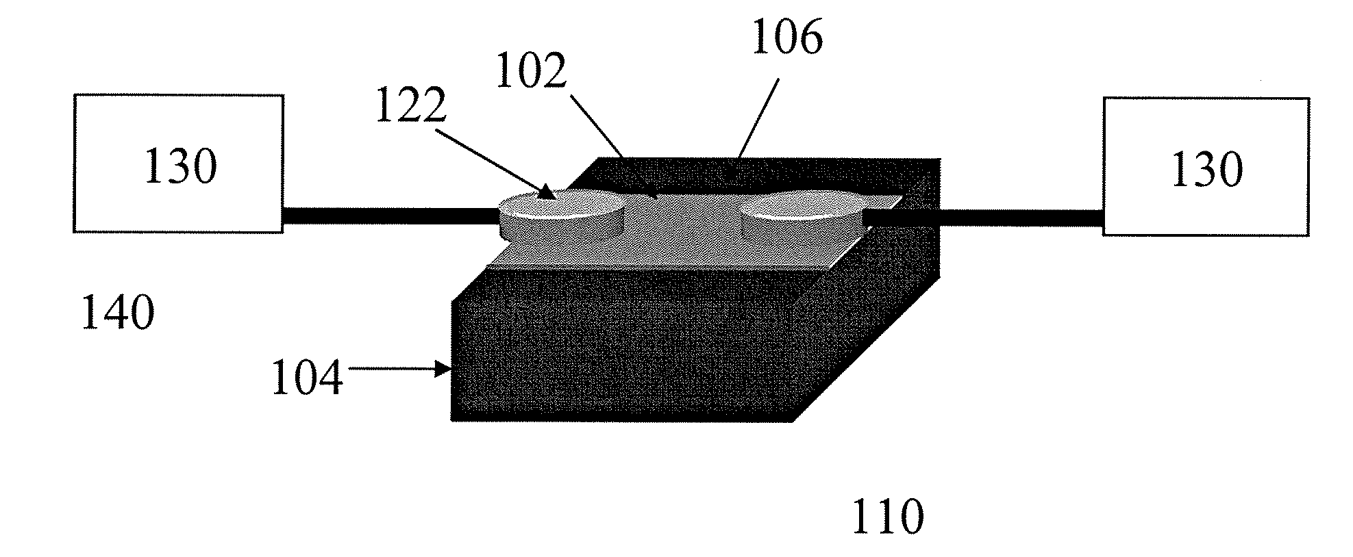
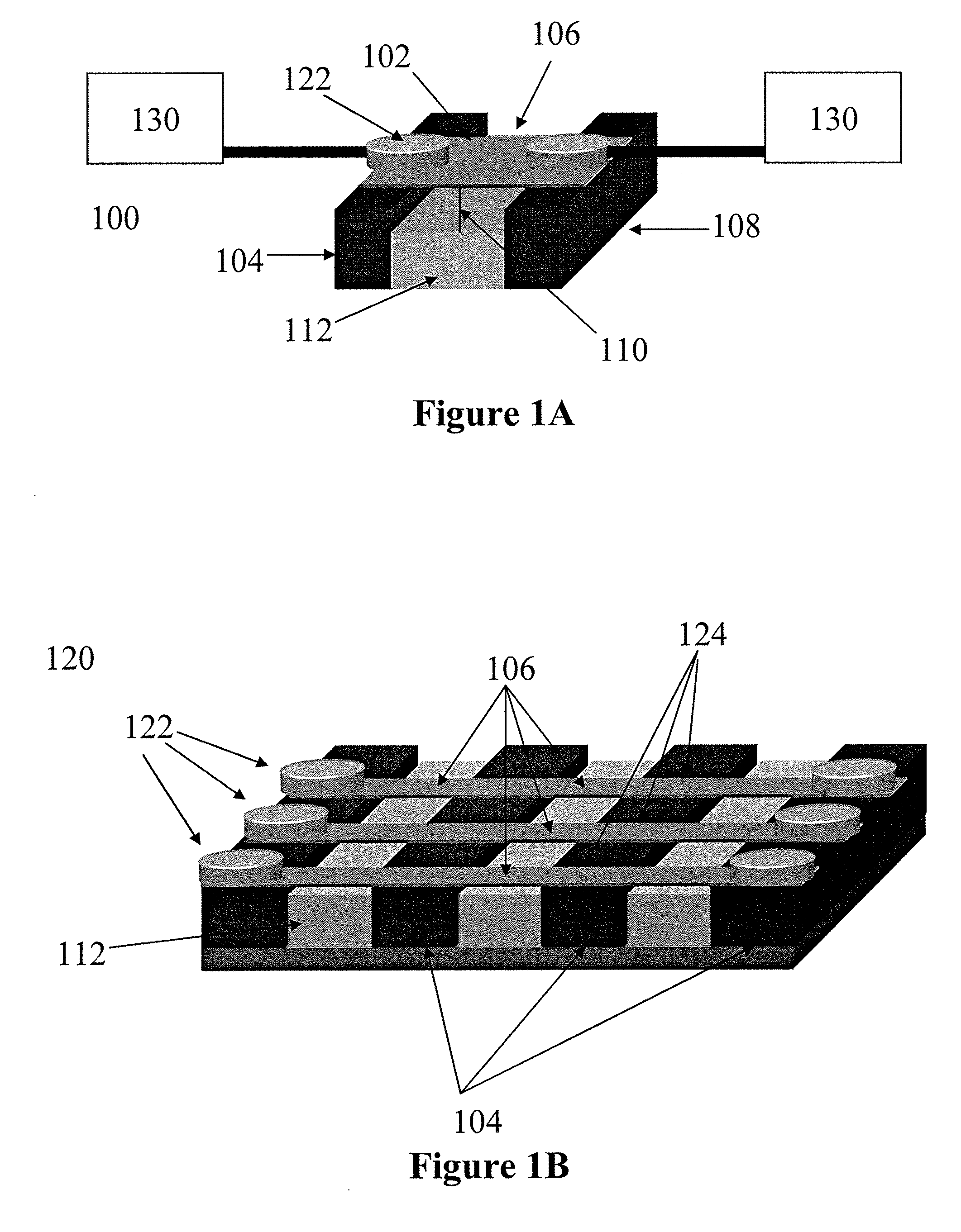
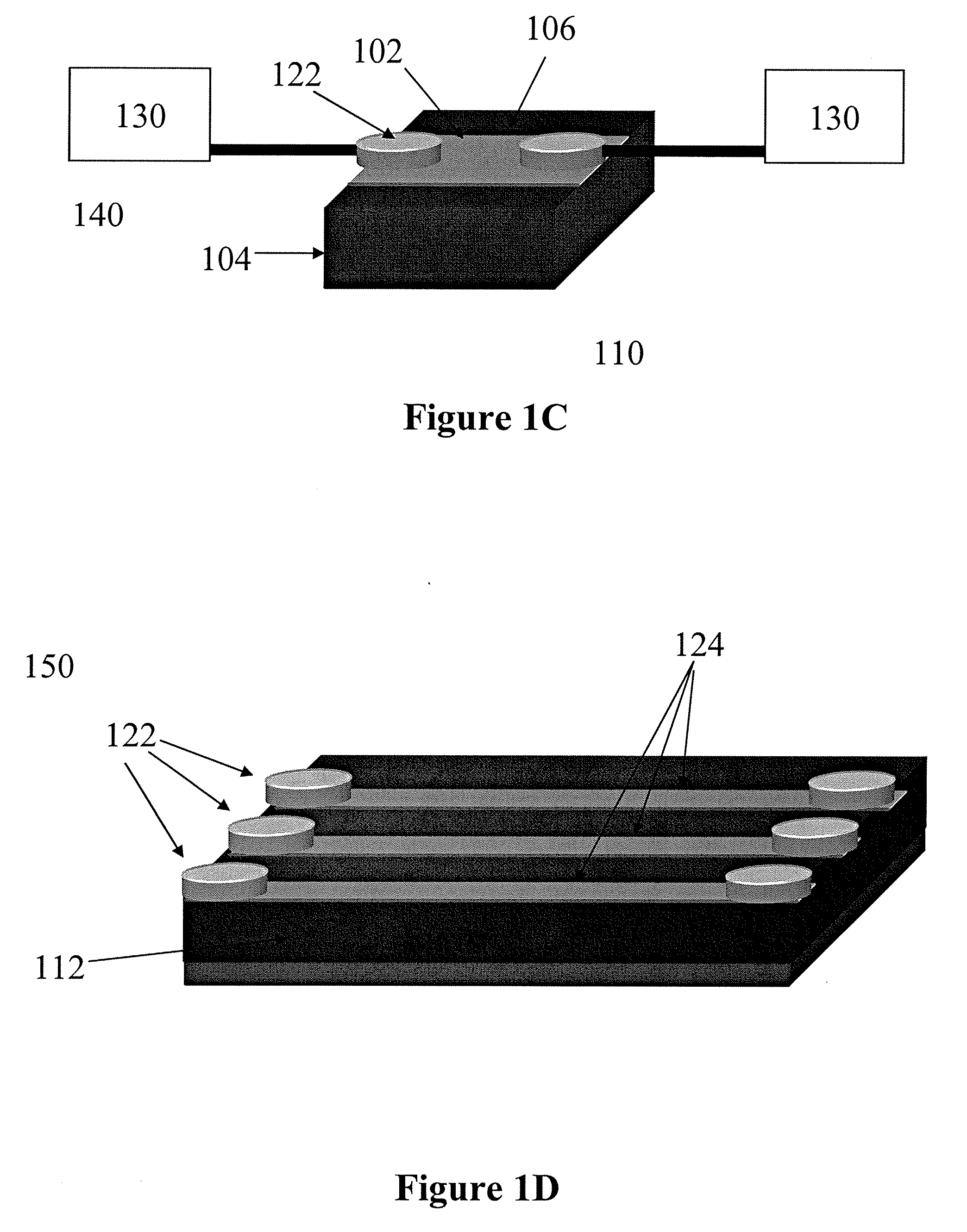
[0105]Various embodiments of the invention provide carbon nanotube fabrics for use in electromagnetic radiation detecting and sensing systems and methods of making the same.

[0106]Broad-range electromagnetic radiation sensors and detectors may be constructed with nanotube fabrics. Carbon nanotubes have unique electrical and thermal properties that make them excellent materials for electromagnetic radiation and, specifically thermal detection. Fabrics constructed from carbon nanotubes have the capability of sensing a wide spectrum of radiation, from Gamma Rays (□0.1 cm). With very low metal contamination levels, nanotube fabrics can be readily deposited on a variety of substrates and can be integrated with CMOS technology. The attributes of carbon nanotubes and carbon nanotube fabrics make them an excellent and high-performance material when used in electromagnetic and thermal detectors. The performance advantages of detectors (e.g. microbolometers) constructed with carbon nanotube fa...


PUM


Abstract

Electromagnetic radiation detecting and sensing systems using carbon nanotube fabrics and methods of making the same are provided. In certain embodiments of the invention, an electromagnetic radiation detector includes a substrate, a nanotube fabric disposed on the substrate, the nanotube fabric comprising a non-woven network of nanotubes, and first and second conductive terminals, each in electrical communication with the nanotube fabric, the first and second conductive terminals disposed in space relation to one another. Nanotube fabrics may be tuned to be sensitive to a predetermined range of electromagnetic radiation such that exposure to the electromagnetic radiation induces a change in impedance between the first and second conductive terminals. The detectors include microbolometers, themistors and resistive thermal sensors, each constructed with nanotube fabric. Nanotube fabric detector arrays may be formed for broad-range electromagnetic radiation detecting. Methods for making nanotube fabric detectors, arrays, microbolometers, thermistors and resistive thermal sensors are each described.

Description

CROSS-REFERENCE TO RELATED APPLICATIONS[0001]This application claims priority under 35 U.S.C. § 119(e) to U.S. Provisional Patent Application No. 60 / 906,409, filed on Mar. 12, 2007, entitled “Electromagnetic Thermal Sensors Using Carbon Nanotubes and Methods of Making Same,” which is incorporated herein by reference in its entirety.BACKGROUND[0002]1. Technical Field[0003]The present application relates generally to nanotube fabrics and methods of making same and, more specifically to carbon nanotube fabrics and methods of making same for use in electromagnetic radiation detecting and sensing systems.[0004]2. Discussion of Related Art[0005]Detectors are an integral part of optical circuits and components (emitters, modulators, repeaters, waveguides or fibers, reflectors, resonators, etc.) and are used for the sensing of electromagnetic (EM) radiation. Photoconducting materials, typically semiconductors, have electrical properties that vary when exposed to EM radiation (i.e. UV, visib...

Claims


Application Information

Patent Timeline
IPC IPC(8): H01L27/144H01L31/18H01L31/0264
CPCG01J5/02G01J5/023G01J5/046G01J5/08G01J5/0846G01J5/0853G01J5/20G01J5/24G01T1/16
Inventor WARD, JONATHAN W.EGERTON, ELWOOD JAMESSEN, RAHULSEGAL, BRENT M.
Owner NANTERO
Why Eureka
Try Eureka