Fluorescent Lamp, Backlight Unit and Liquid Crystal Television

Inactive Publication Date: 2008-10-16
PANASONIC CORP
View PDF9 Cites 7 Cited by
  • Summary
  • Abstract
  • Description
  • Claims
  • Application Information

AI Technical Summary

Benefits of technology

[0006]That is, due to a discharge that accompanies lighting of the lamp, cesium is released from the cesium compound applied to the inner, near-electrode surface of the glass bulb. The released cesium scatters, attaching to a phosphor layer of the aforementioned light-emitting area. As cesium is yellow and has a low translucency, the phosphor layer with the cesium attached thereto will naturally end up in having a lower translucency. At the early stage of lamp life, this will, over time, reduce luminous flux generated by the lamp during operation.
[0007]In addition to the time-proportional decrease in the luminous flux, the inventors have also discovered from the examinatio

Problems solved by technology

In darkness, these fluorescent lamps do not operate instantly after a starting voltage is applied thereto; it takes a w

Method used


Image

  • Fluorescent Lamp, Backlight Unit and Liquid Crystal Television
  • Fluorescent Lamp, Backlight Unit and Liquid Crystal Television
  • Fluorescent Lamp, Backlight Unit and Liquid Crystal Television

Examples


Example

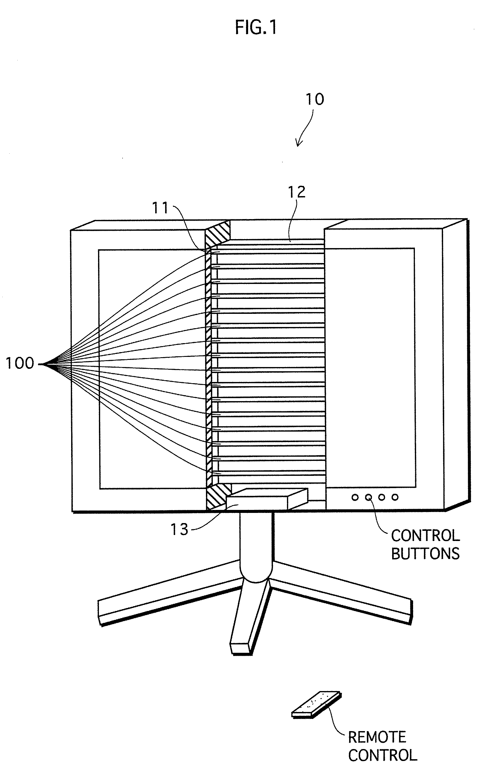
[0053]FIG. 1 shows an overview of a liquid crystal television pertaining to a first embodiment of the present invention.

[0054]A liquid crystal television 10 shown in FIG. 1 is, for example, a 32-inch liquid crystal television, and includes a liquid crystal display unit 11 and a backlight unit 12.

[0055]The liquid crystal display unit 11 is composed of a color filter substrate, a liquid crystal, a TFT substrate, a drive module (not illustrated) etc., and forms color images based on an external image signal.

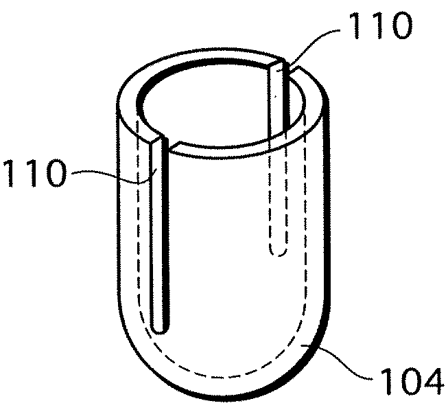
[0056]The backlight unit 12 is an LCBL unit and composed of one high-frequency electronic ballast 13 and sixteen dielectric barrier discharge lamps 100 (hereafter, simply “fluorescent lamp 100”).

[0057]The high-frequency electronic ballast 13 is a lighting circuit that operates all of the sixteen fluorescent lamps 100.

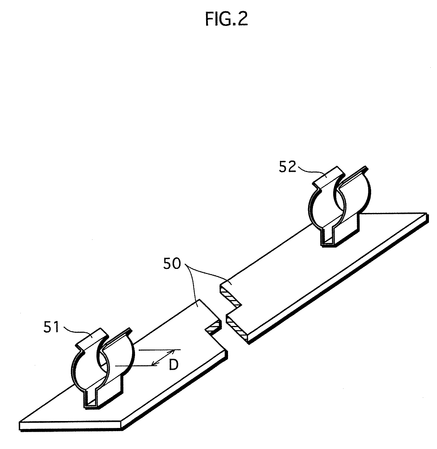
[0058]A socket board 50 shown in FIG. 2 has electrode sockets 51 and 52 made of elastic stainless steel, phosphor bronze, etc. The electrode sockets 51 and 52 hold both...

Example

Second Embodiment

[0123]In the above-described first embodiment, the phosphor layer 106 is provided directly on the inner surface of the glass bulb 101. In contrast, a dielectric barrier discharge lamp pertaining to the second embodiment has a protective layer and a phosphor layer provided on an inner surface thereof in listed order.

[0124]FIG. 7 shows an overview of a dielectric barrier discharge lamp 200 pertaining to the second embodiment.

[0125]The lamp 200 in FIG. 7 is constructed fundamentally the same as the fluorescent lamp 100 in FIG. 3. Although the elements shown in FIG. 3 are numbered 100s while the elements shown in FIG. 7 are numbered 200s, numbers of the corresponding elements have the same last two figures for the sake of simple explanation.

[0126]The lamp 200 has a tube-shaped glass bulb 201.

[0127]A protective layer 211 and a phosphor layer 206 are provided, in listed order, on the inner surface of the glass bulb. More specifically, the phosphor layer 206 is provided on...

Example

Third Embodiment

[0165]The first and second embodiments have described the dielectric barrier discharge lamp as one example of a fluorescent lamp. However, the present invention is not limited to such, but instead may be realized with use of a cold cathode fluorescent lamp. The following describes the third embodiment.

[0166]FIG. 10 shows an overview of a cold cathode fluorescent lamp 300 pertaining to the third embodiment.

[0167]The cold cathode fluorescent lamp 300 has a straight tube-shaped glass bulb 301 that is made of soda glass. The glass bulb 301, for example, has a total length of 450 mm, an outer diameter of 3.0 mm, an inner diameter of 2.0 mm, and a wall-thickness of 0.5 mm.

[0168]Leads 314 and 316 are sealed by both end portions of the glass bulb 301.

[0169]The lead 314 (316) is a wire composed of an internal lead 314A (316A) made of tungsten and an external lead 314B (316B) made of nickel. The internal leads 314A and 316A have glass containers 12. Inner surfaces of end porti...


PUM

PropertyMeasurementUnit
Fractionaaaaaaaaaa
Fractionaaaaaaaaaa
Thicknessaaaaaaaaaa

Abstract

The present invention relates to a fluorescent lamp, and in particular to a fluorescent lamp with an improved in-dark starting characteristic. A fluorescent lamp includes: a glass bulb (101) having a discharge space therein; two external electrodes (102 and 103) provided at both ends of the glass bulb; and a phosphor layer (106) provided on an inner surface of the glass bulb. The glass bulb is made of glass that contains 3% to 20% inclusive of sodium oxide. The phosphor layer includes phosphor particles (106R and 106G) containing no alumina and phosphor particles (106B) containing alumina. A metal oxide (107) is attached to surfaces of the phosphor particles containing alumina. Sodium oxide precipitated on the inner surface of the glass bulb improves the in-dark starting characteristic. The phosphor particles containing alumina are protected by the metal oxide for being susceptible to deterioration due to reaction thereof with sodium oxide.

Description

TECHNICAL FIELD[0001]The present invention relates to a fluorescent lamp having a tube-shaped glass bulb whose both ends are provided with electrodes, a backlight unit, and a liquid crystal television.BACKGROUND ART[0002]As a display of the liquid crystal television has become larger in recent years, there has been increasing demand for a backlight unit designed for a large-screen liquid crystal television. Examples of lamps that have been practically used for the backlight unit include a fluorescent lamp having a glass bulb that includes electrodes mounted outside the glass bulb (i.e., an external electrode fluorescent lamp), and a fluorescent lamp having a glass bulb that includes electrodes mounted inside the glass bulb (i.e., a cold cathode fluorescent lamp).[0003]In darkness, these fluorescent lamps do not operate instantly after a starting voltage is applied thereto; it takes a while for them to give off light. In other words, the above fluorescent lamps have poor in-dark star...

Claims


Application Information

Patent Timeline
IPC IPC(8): H01J63/04H01J17/20F21S2/00H01J5/50H01J61/30H01J61/35H01J61/44H01J61/46H01J65/00
CPCC03C3/00C09K11/025C09K11/7734C09K11/7777C09K11/7787H01J61/302H01J61/44H01J65/00
Inventor YAMADA, KENJIONO, TAIZOUARATA, HIROYUKIWADA, HIDEKIMATSUO, KAZUHIROMATSUURA, TOMOKAZUTERADA, TOSHIHIRO
Owner PANASONIC CORP
Why Eureka
Try Eureka