Supercharge Your Innovation With Domain-Expert AI Agents!

Electron emitter, field emission display unit, cold cathode fluorescent tube, flat type lighting device, and electron emitting material

a field emission display unit and electron emitting material technology, applied in the field of electron emitters, to achieve the effect of low driving voltage, convenient preparation, and convenient preparation

Inactive Publication Date: 2008-10-16
ASAHI GLASS CO LTD
View PDF2 Cites 9 Cited by
  • Summary
  • Abstract
  • Description
  • Claims
  • Application Information

AI Technical Summary

Benefits of technology

[0022]According to the present invention, it is possible to obtain an electron emission material which is easy to prepare and is capable of emitting electrons at a low driving voltage. By using this electron emitting material, it is possible to obtain an electron emitter which is easy to prepare and capable of emitting electrons even at a low applied voltage and whereby a large emission current can be obtained per the same applied voltage. Further, it is possible to realize a field emission display unit, a cold cathode fluorescent tube and a flat type lighting device, which is easy to prepare and can be driven at a low voltage.

Problems solved by technology

However, a sharp-pointed electron emitter is difficult in processing into an electrode, and if the electrode spacing is reduced, a problem is likely to result in the preparation of the element or in the reliability, whereby it has been difficult to produce electron emitters, or FED or a cold cathode fluorescent tube employing them.

Method used


Image

  • Electron emitter, field emission display unit, cold cathode fluorescent tube, flat type lighting device, and electron emitting material
  • Electron emitter, field emission display unit, cold cathode fluorescent tube, flat type lighting device, and electron emitting material
  • Electron emitter, field emission display unit, cold cathode fluorescent tube, flat type lighting device, and electron emitting material

Examples


example 1

[0103]Firstly, in accordance with a prescribed method, to a glass material of a composition comprising 61.0 mol % of CaO, 35.3 mol % of Al2O3 and 3.7 mol % of SiO2, as calculated as oxides, a carbon powder was added in an amount of 0.8% as a ratio in the number of atoms to the total number of atoms of Ca, Al and Si in this glass material, to prepare a carbon-containing calcium aluminate glass material. Then, this material was melted at 1,650° C. and vitrified to obtain a bulky carbon-containing calcium aluminate glass. The obtained glass was analyzed by Raman spectroscopy, whereby it was found that carbon was contained in the state of C22− ions in the glass. Further, by the secondary ion analysis and the combustion analysis, the carbon atoms contained in the obtained glass were confirmed to be 0.5% as a ratio in the number of atoms to the total number of atoms of Ca, Al and Si in this glass.

[0104]This carbon-containing calcium aluminate glass was roughly pulverized to the maximum pa...

example 2

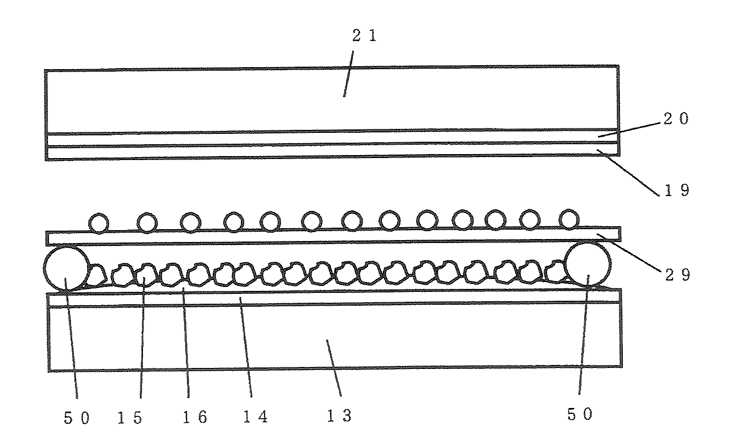
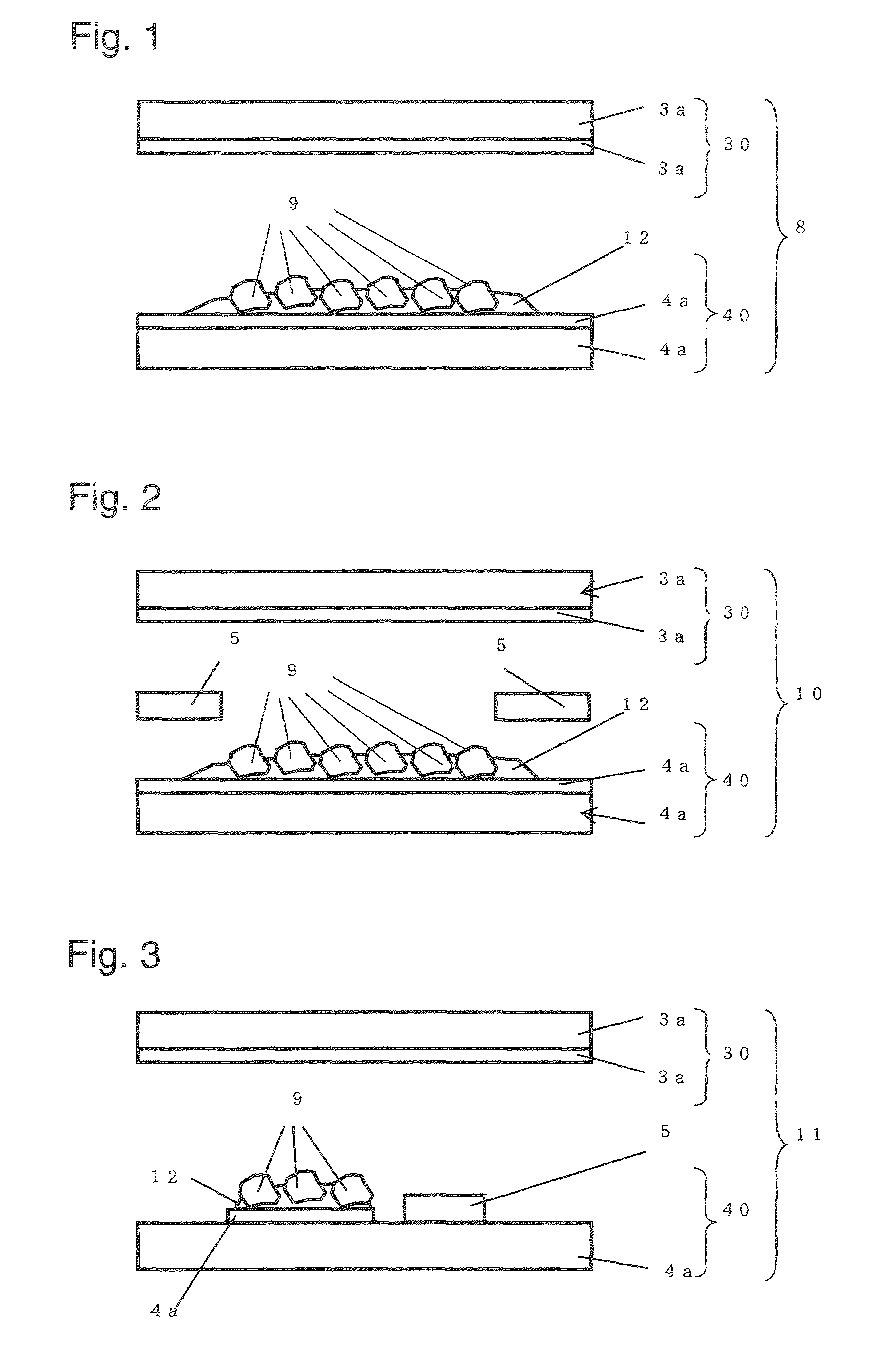
[0105]By using the conductive mayenite type compound powder in Example 1, a micro electron source 8 of diode structure as shown in FIG. 1, was prepared. A transparent electrode-coated glass substrate 4 having a transparent electrode of ITO formed on one side, was prepared; on the transparent electrode 4a, a conductive paste (Dotite, manufactured by Fujikura Kasei Co., Ltd.) was applied; and on the applied conductive paste, this powder was sprinkled. Then, this substrate was evacuated to a vacuum degree of at most 5×10⁻⁴ Pa to sufficiently evaporate the solvent and to solidify the conductive paste, to obtain an emitter panel 10 of this Example. By the above steps, electron emitters 9 made of the conductive mayenite type compound powder were fixed on the negative electrode 4a by a conductive adhesive layer 12 made of the solidified conductive pastes, with the surface being exposed.

[0106]Another sheet of the same transparent electrode-coated glass substrate was prepared to be used as a...

example 3

[0107]In the same manner as in Example 1, a bulky carbon-containing calcium aluminate glass was prepared. The prepared bulky glass was put in a carbon crucible and subjected to heat treatment by holding it in a nitrogen atmosphere of 1,300° C. for 3 hours, and then left to cool in the furnace to obtain a bulky conductive mayenite type compound.

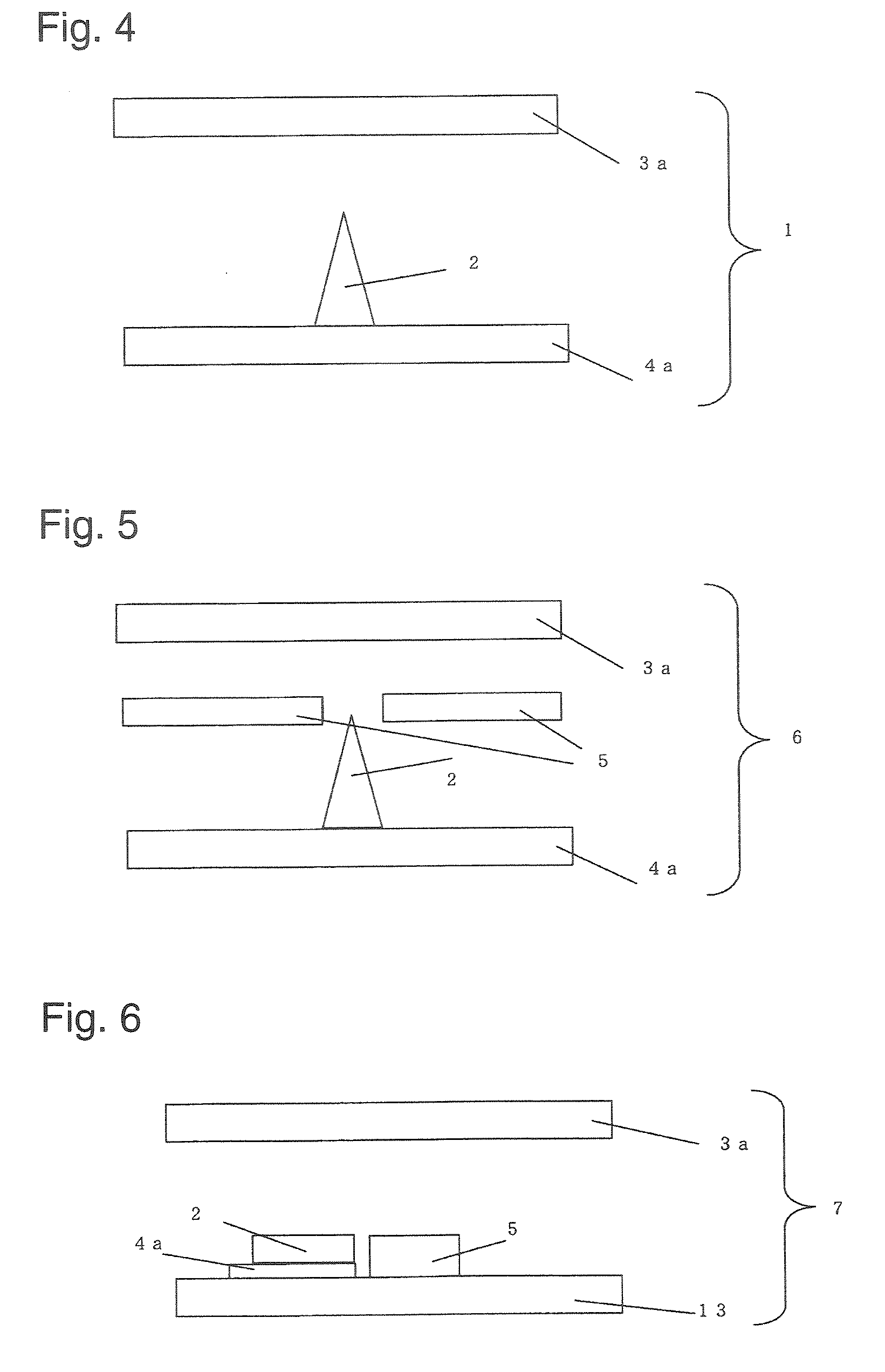
[0108]The obtained conductive mayenite type compound was crushed to have a pyramid shape, and by using it, a microelectron source 1 having the structure of FIG. 4 was prepared. Namely, a transparent electrode-coated glass substrate 4 having a transparent electrode made of ITO formed on one side, was prepared. On the transparent electrode of this transparent electrode-coated glass substrate 4, the pyramid-shaped conductive mayenite type compound was fixed so that the apex of the pyramid shape was located above, to form an electron emitter 2 of this Example. Then, the emitter panel was evacuated in a vacuum container to a vacuum degree of at mos...


PUM

PropertyMeasurementUnit
Lengthaaaaaaaaaa
Pressureaaaaaaaaaa
Fractionaaaaaaaaaa

Abstract

To provide an electron emitter, a field emission display unit, a cold cathode fluorescent tube and a flat type lighting device, which employ an electron emitting material producible at a low cost and in a large amount.A conductive mayenite type compound powder containing at least 50 mol % of a mayenite type compound represented by a chemical formula of either 12CaO.7Al2O3 or 12SrO.7Al2O3 and having a maximum particle size of at most 100 μm, is used as an electron emitter, whereby an electron emitter, a field emission display unit, a cold cathode fluorescent tube and a flat type lighting device, are realized that are easy to produce and capable of emitting electrons even at a low applied voltage and whereby a large current can be obtained per the same applied voltage surface.

Description

TECHNICAL FIELD[0001]The present invention relates to an electron emitter, a field emission display unit, a cold cathode fluorescent tube, a flat type lighting device, and an electron emitting material.BACKGROUND ART[0002]A field emission display unit (hereinafter referred to as FED) has a large array of micro electron sources provided with micron size electron emitters to emit electrons for every pixel, so that phosphors on positive electrodes disposed to face the micro electron sources are excited by the electron beams to glow thereby to display an image. A highly precise display is thereby possible, and it can be made to be far thinner than a CRT panel. Thus, FED is expected to be a large screen flat display. Whereas, a cold cathode fluorescent tube or a flat type lighting device uses micro electron sources provided with electron emitters which emit electrons by an intense electric field, and by reducing the tube diameter, the luminance can be made high, and at the same time, the...

Claims


Application Information

Patent Timeline
IPC IPC(8): H01J1/62H01J1/02C04B35/00
CPCH01J1/304H01J9/025H01J31/127H01J63/02H01J2201/30446H01J63/06H01J31/15H01J31/12
Inventor KUROIWA, YUTAKANARUSHIMA, SATORUITO, SETSURO
Owner ASAHI GLASS CO LTD
Features
  • R&D
  • Intellectual Property
  • Life Sciences
  • Materials
  • Tech Scout
  • Unparalleled Data Quality
  • Higher Quality Content
  • 60% Fewer Hallucinations
Learn More