Self-regulating bio-gas treatment system

Inactive Publication Date: 2008-10-23
SNAP ENERGY SYST
View PDF39 Cites 17 Cited by
  • Summary
  • Abstract
  • Description
  • Claims
  • Application Information

AI Technical Summary

Benefits of technology

[0008]These and other objects of the invention are met by a self-regenerating bio-gas treatment system disclosed herein that uses a recyclable, fluidized, solid media transport to remove contaminates fro

Problems solved by technology

A major drawback of utilizing bio-gas from these sources is the contamination of the gas from volatile chemicals that fall into one of three major groups: volatile organic contaminants (such as benzene, toluene and xylene compounds known as ‘BTEX’); volatile inorganic contaminants (such as hydrogen sulfide); and volatile species containing silicon or organosilicons (such as the silanes, silanols, and siloxanes).
All three major groups of contaminants are undesirable due to various deleterious properties like corrosivity, toxicity, and physical abrasion to power generation equipment.
The organosilicons are the most damaging, often sign

Method used


Image

  • Self-regulating bio-gas treatment system
  • Self-regulating bio-gas treatment system

Examples


Embodiment Construction

)

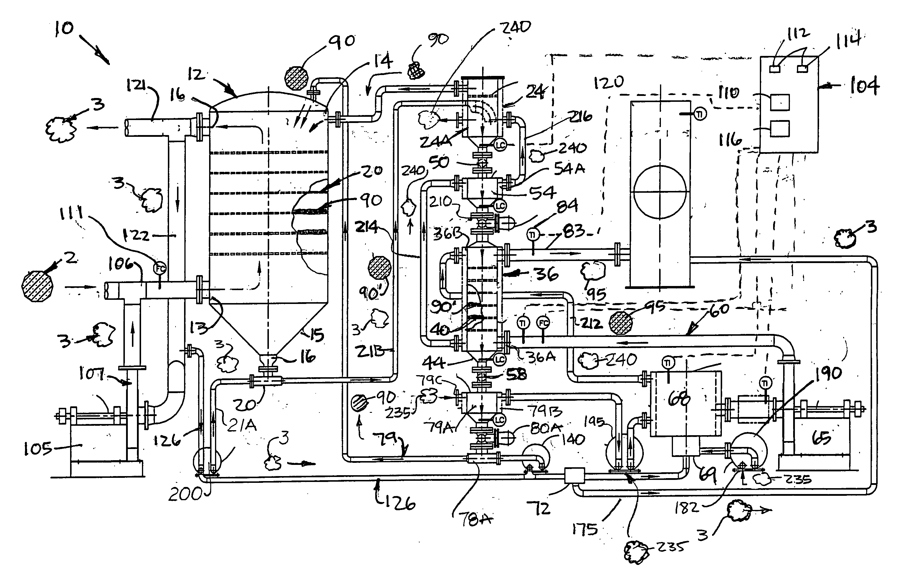
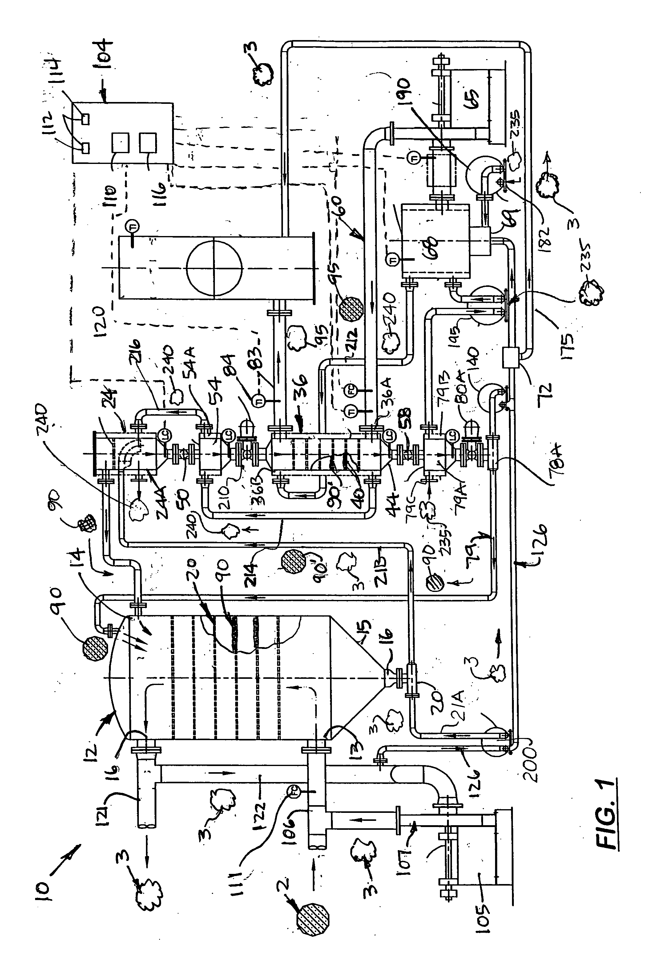
[0013]Referring to FIG. 1 there is shown a self-regenerating bio-gas treatment system 10 that includes a closed and separate adsorber tank 12 and a desorber tank 36. Each tank 12, 36 includes at least four transversely aligned, stacked and evenly spaced apart, perforated trays 20, 40, respectively each capable being filled with pelletized carbon or silica gel material, hereinafter called transport media 90. During use, raw, contaminated bio-gas 2 enters the adsorber tank 12 through a lower inlet opening 13 at the bottom of the tank 12. Located at the top of the adbsorber tank 12 is an upper inlet opening 14 through which the transport media 90 is delivered. The transport media 90 has sufficient small particle size so that it fills, end eventual falls over the edges of the trays 20. Optional perforations are formed in the trays to allow bio-gas to seep through the layer of transport media deposited on the tray 20. The transport media 90 is continuously added to the absorber tank 12 ...


PUM

PropertyMeasurementUnit
Fractionaaaaaaaaaa

Abstract

A self-regenerating bio-gas treatment system that uses the bio-gas instead of atmospheric are as media transport between adsorber and desorber tanks. Each tank includes at least four horizontally stacked and evenly spaced apart, perforated trays each capable being filled with fluidized carbon which migrates downward in the adsorber tank to remove contaminants from the bio-gas. With the bio-gas function as its media transport, the carbon media continuously moves downward over the perforated trays and eventually collected in the bottom of the adsorber tank. The spent carbon is then delivered to the desorber tank. The desorber tank is filled with an inert gas produced by an inert gas generator which causes the carbon media to be regenerated. The inert gas strips the carbon media of contaminates and is then delivered to a ground flare. The carbon media is returned to the adsorber tank and re-used to treat bio-gas. A plurality of heat exchangers, blowers, valves and interconnecting conduits keep the bio-gas, the inert gas, and the carbon media continuously flowing through the system thereby enabling the system to be used at different sizes of landfills or treatment plants.

Description

[0001]This is a utility patent application which claims benefit of U.S. Provisional Application No. 60 / 925,969 filed on Apr. 23, 2007.BACKGROUND OF THE INVENTION 1. Field of the Invention[0002]This invention relates to systems for processing organic material, and more particularly to such systems that reduce emissions of bio-gas and the parasite load on landfills.[0003]2. Description of the Related Art[0004]The recent increase in energy prices has resulted in an increased focus on the use of energy from renewable sources. In particular, the generation of power from bio-gas sources, such as municipal digester and landfills, has become increasingly popular.[0005]A major drawback of utilizing bio-gas from these sources is the contamination of the gas from volatile chemicals that fall into one of three major groups: volatile organic contaminants (such as benzene, toluene and xylene compounds known as ‘BTEX’); volatile inorganic contaminants (such as hydrogen sulfide); and volatile speci...

Claims


Application Information

Patent Timeline
IPC IPC(8): B01D53/26
CPCB01D53/04B01D2253/102B01D2258/05B01D2259/4009Y02C20/20
Inventor HOWARD, LOWELL
Owner SNAP ENERGY SYST
Why Eureka
Try Eureka