Pulse output circuit, shift register, and display device
a shift register and output circuit technology, applied in pulse techniques, generating/distributing signals, instruments, etc., can solve problems such as malfunction, tft b>1020/b> may be turned, and circuit malfunctions, etc., to achieve high frequency, suppress the effect of malfunction of pulse output circuits, and withstand large loads
- Summary
- Abstract
- Description
- Claims
- Application Information
AI Technical Summary
Benefits of technology
Problems solved by technology
Method used
Image
Examples
embodiment mode 1
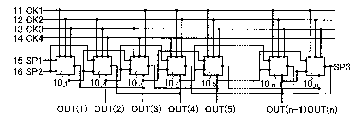
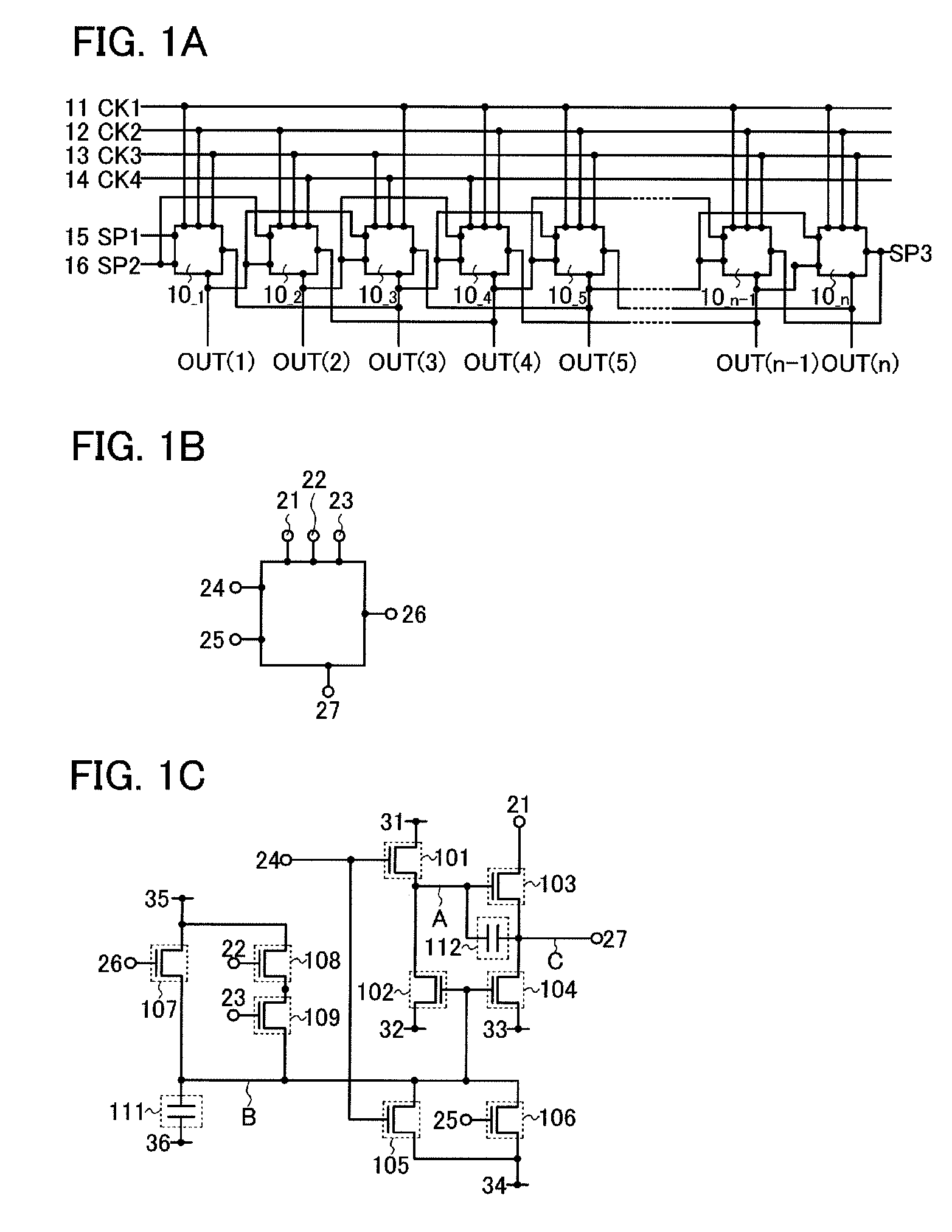
[0039]In this embodiment mode, an example of a pulse output circuit of the present invention and a shift register including the pulse output circuit will be described with reference to drawings.
[0040]A shift register shown in this embodiment mode includes first to n-th pulse output circuits 10—1 to 10—n (n≧3) and first to fourth signal lines 11 to 14 each of which outputs a clock signal (see FIG. 1A). The first signal line 11 outputs a first clock signal (CK1), the second signal line 12 outputs a second clock signal (CK2), the third signal line 13 outputs a third clock signal (CK3), and the fourth signal line 14 outputs a fourth clock signal (CK4).
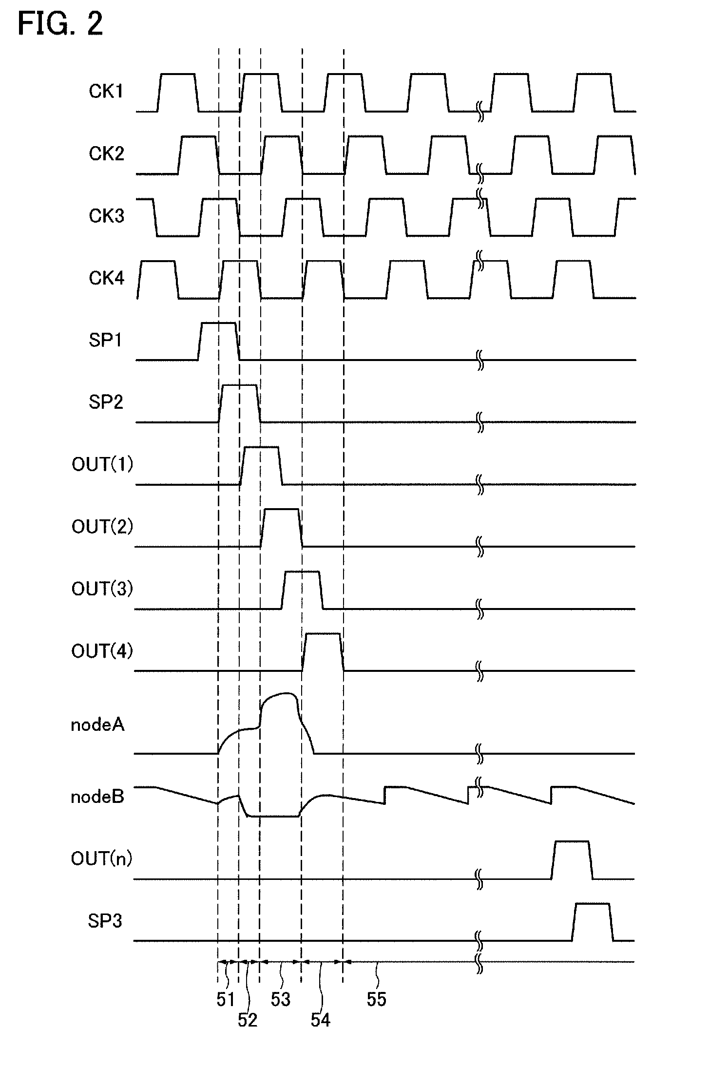
[0041]The clock signals (CK) are signals which alternate between an H (High) signal and an L (Low) signal at a regular interval, and here, the first to fourth clock signals (CK1) to (CK4) are delayed for ½ period sequentially. In this embodiment mode, by using the first to fourth clock signals (CK1) to (CK4), control or the like of driving...
embodiment mode 2
[0072]In this embodiment mode, structures of a shift register and a pulse output circuit which are different from those in the above embodiment mode will be described with reference to drawings.
[0073]A shift register shown in this embodiment mode includes the first to n-th pulse output circuits 10—1 to 10—n (n≧3) and the first to fourth signal lines 11 to 14 each of which outputs a clock signal (see FIG. 6A). In addition, each of the first to n-th pulse output circuits 10—1 to 10—n includes the first input terminal 21, the second input terminal 22, the third input terminal 23, the fourth input terminal 24, the fifth input terminal 25, the sixth input terminal 26, the first output terminal 27, and a second output terminal 28 (see FIG. 6B). Note that the shift register in this embodiment mode has a structure in which the second output terminal 28 is added to the pulse output circuit described in Embodiment Mode 1.
[0074]The first input terminal 21, the second input terminal 22, and the...
embodiment mode 3
[0083]In this embodiment mode, structures of a shift register and a pulse output circuit which are different from those in the above embodiment modes will be described.
[0084]In the structures described in Embodiment Modes 1 and 2, the examples in which all of the circuits are formed using N-channel thin film transistors are shown; however, a similar structure may be used in which only P-channel thin film transistors are used in terms of using unipolar thin film transistors. Although not shown in particular, in FIG. 1C or FIG. 6C, connection of the transistors is the same, and high and low level potentials of a power source line may be inverted to the cases described in Embodiment Modes 1 and 2. In addition, a structure may be used in which H level signals to be inputted and L level signals to be inputted are all inverted and inputted. Note that the present invention in this embodiment mode can be also applied to a semiconductor device.
PUM
 Abstract
Description
Claims
Application Information
 - R&D
- Intellectual Property
- Life Sciences
- Materials
- Tech Scout
- Unparalleled Data Quality
- Higher Quality Content
- 60% Fewer Hallucinations
Browse by: Latest US Patents, China's latest patents, Technical Efficacy Thesaurus, Application Domain, Technology Topic, Popular Technical Reports.
© 2025 PatSnap. All rights reserved.Legal|Privacy policy|Modern Slavery Act Transparency Statement|Sitemap|About US| Contact US: help@patsnap.com


