[0009]The present invention is directed to a method of combustion that has one or more advantages of low NOx emission, low unburned carbon, automatic adaptability to any types of
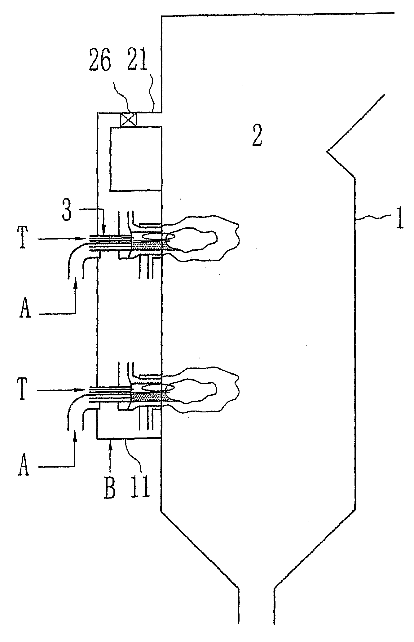
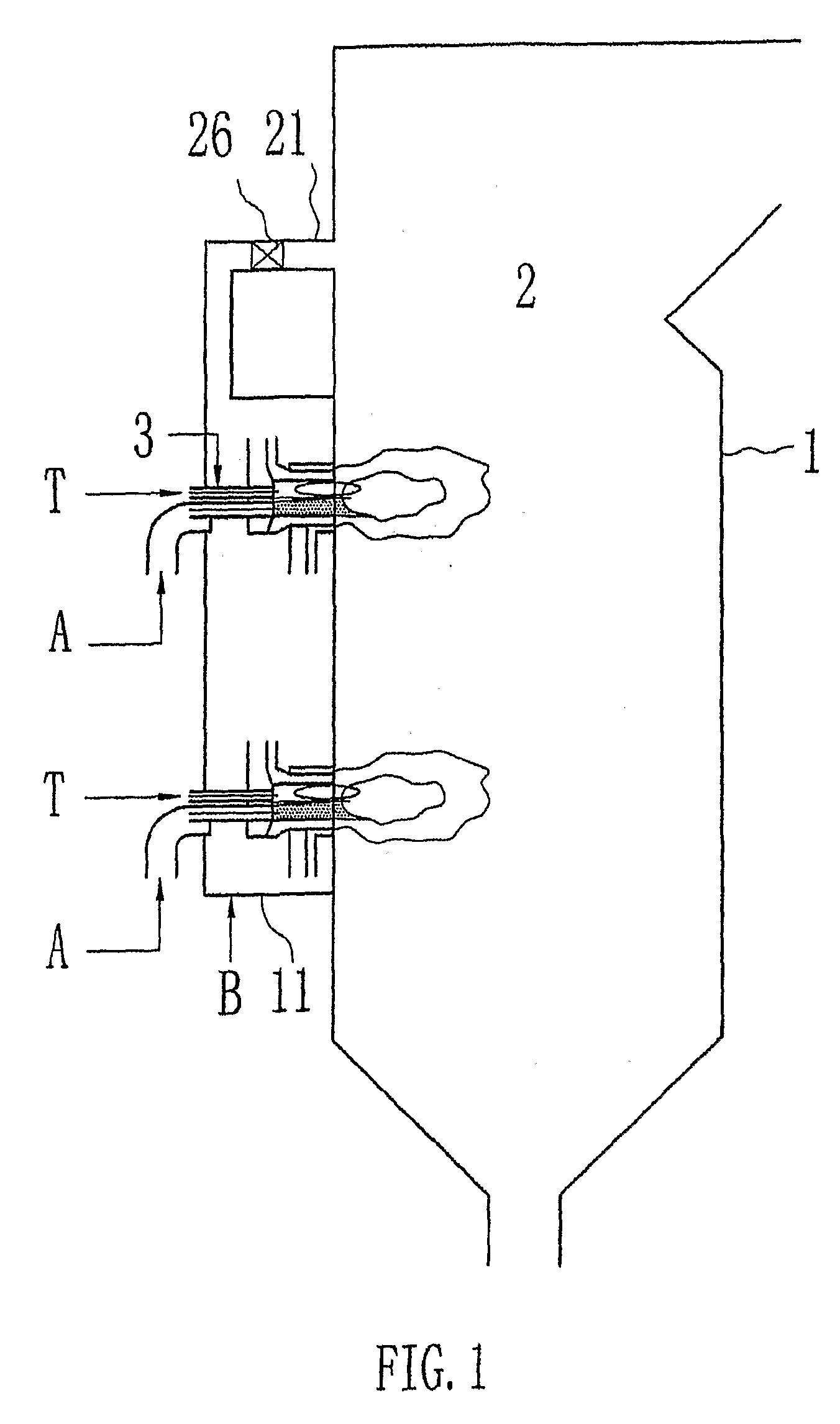
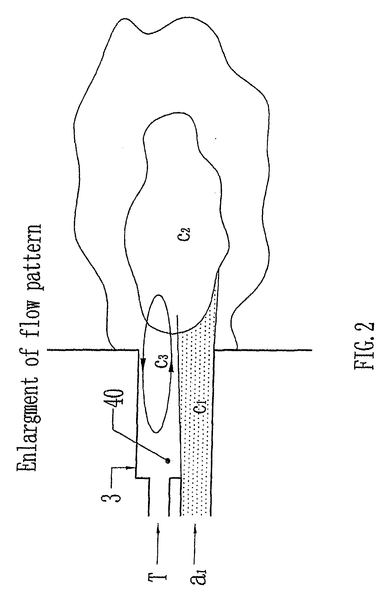
fossil fuel, and reduced slagging. The combustion method may include injecting an oxidant / fuel stream into a burner to cause a low-pressure zone; directing a flow of a high-temperature combustion gas from a combustion chamber into the low-pressure zone in the burner; mixing the high-temperature combustion gas with the injected oxidant / fuel stream to heat the injected air / fuel stream, and injecting the heated oxidant / fuel stream from the burner to the combustion chamber, wherein the air / fuel stream is rapidly devolatilized and combusted in a flame; sensing a combustion parameter; and based on the sensed combustion parameter, controlling the combustion to achieve at least one of a desired NOx reduction and a desired distance from the burner to a front of the flame. In a preferred embodiment, the combustion is controlled to maximize NOx reduction without impermissible slagging. What constitutes “impermissible slagging” cannot be determined in the abstract and must be determined on a case-by-case basis from the design requirements for a given
combustion system. Such a determination can be made by a person with ordinary skill in the art.
[0011]In a preferred embodiment, the velocity of the injected oxidant / fuel stream in the burner is 10 to 60 m / sec, more preferably 15 to 50 m / sec. The velocity can be designed so as to feed the oxidant / fuel stream without blocking the feed
pipe, and to introduce a pressure inside the burner that is lower than that in the combustion chamber. The cross-sectional area of the injection at the entrance of the burner may be a fraction of the cross-sectional area of the burner, preferably 20% to 60%. The desirable ratio of the two cross-sectional areas allows a certain amount of high-temperature combustion gas to flow back into the burner from the combustion chamber.
[0013]In another preferred embodiment, the oxidant is
pure oxygen, and the
oxygen / fuel stream is a concentrated
oxygen / fuel stream, i.e., an
oxygen / fuel stream having a
low oxygen to fuel ratio. Preferably, the ratio of oxygen to fuel solids in the concentrated stream is 0.08 to 0.44 kg oxygen / 1 kg fuel, more preferably 0.12 to 0.30 kg oxygen / 1 kg fuel. There are several reasons for the use of a concentrated oxidant / fuel stream. First, the concentrated stream allows the maintenance of a highly fuel-rich flame inside the burner and combustion chambers, which can significantly reduce the NOx. Secondly, the concentrated stream can be heated up using a relatively small amount of heat. Thus the concentrated stream can be quickly heated up in a
short distance. Third, the heated concentrated stream releases a large amount of
volatiles in the fast heating. (Partial combustion also may take place during the heating of the concentrated stream.) The released
volatiles enhance the ignition and combustion of fuel particles, such as coal particles, reducing the unburned carbon in
fly ash. Additionally, a
fast release of
volatiles including fuel-bound nitrogen in the fuel rich
atmosphere allows transformation of the fuel-bound nitrogen into N2 rather than NOx. The overall effects of the concentrated air / fuel stream and the designed burner allow combustion to be performed and maintained at a high temperature and in an
atmosphere of reduced gases, which is conductible to ultra-low NOx emission and low unburned carbon in
fly ash.
[0021]
Combustion control can be achieved by controlling the pressure in the low-pressure zone, because the pressure in the low-pressure zone affects the flow rate of the high-temperature combustion gas from the combustion chamber into the low-pressure zone in the burner and, thus, the heating of the air / fuel stream. The pressure in the low-pressure zone can be controlled by introducing a gas into the low pressure reflow zone. Preferably, the gas is air (
tertiary air). When the quantity of
tertiary air is increased, the pressure in the low-pressure zone is also increased, resulting in a decreased flow of the high-temperature combustion gas from the combustion chamber into the low-pressure zone. As a result, the heating of the air / fuel stream is reduced, and combustion temperature may be reduced. The amount of
tertiary air affects also the oxidant / fuel weight ratio of the oxidant / fuel stream, which can also be used for combustion control.
[0023]The combustion control of the present invention can be based on one or more combustion parameters. Representative parameters may be combustion temperature, pressure, and the concentration of one or more selected gases such as
carbon dioxide,
carbon monoxide, oxygen and nitrogen. Preferably, the temperature is used as the combustion parameter. The control may be realized by sensing the value of the combustion parameter inside the burner and / or the combustion chamber, and comparing the sensed value with a preset value. Based on the difference between the sensed value and preset value, the controller, such as a close-loop controller or a
distributed control system, adjusts one or more of the above-discussed
control parameters to reduce the difference. When the difference is reduced, the NOx emission is reduced, and / or a desired distance from the burner to a flame front is maintained to reduce slagging. This
automatic control enables a burner to be used with almost all kinds of fuel without changing the structure of the combustion
system.

