Sintered Ceramics for Mounting Light-Emitting Element

Inactive Publication Date: 2008-10-30
TOKUYAMA CORP
View PDF2 Cites 7 Cited by
  • Summary
  • Abstract
  • Description
  • Claims
  • Application Information

AI Technical Summary

Benefits of technology

[0018]A specific embodiment of the sintered ceramics of the first aspect of the invention may be the one of which specific region contains α-alumina as a main component and a portion other than the specific region contains aluminum nitride as a main component. With the sintered ceramics having the above constitution, it is possible to obtain two effects, i.e. high-reflectance by α-alumina and high thermal conductivity attribu

Problems solved by technology

However, as the silicon substrate absorbs light of which wavelength is 450 nm (blue) ˜560 nm (green

Method used


Image

  • Sintered Ceramics for Mounting Light-Emitting Element
  • Sintered Ceramics for Mounting Light-Emitting Element
  • Sintered Ceramics for Mounting Light-Emitting Element

Examples


Example

EXAMPLE

[0093]Hereinafter, Examples and Comparative examples are described in detail; however, the present invention is not limited by these examples. Various properties evaluated in the Examples and Comparative examples were measured and determined in accordance with the following methods.

[0094](1) Reflectance

[0095]A 60-diameter (φ60) integrating-sphere accessory device (“150-0902”; with barium sulfate application) was set to a spectrophotometer “U-3210” manufactured by Hitachi, Ltd., then diffuse reflectance to light of wavelength in the range of 250 nm˜800 nm was measured in accordance with integrating sphere. As the reference substance (reflectance: 100%), aluminum oxide (sub-white-plate “210-0740” manufactured by Hitachi, Ltd.) was used. The measurement condition was set to Bandpass: 5 nm, Response: Medium, and Scanning speed: 15 nm / min.

[0096](2) Tape Peeling Test

[0097]Test tape used for the Peeling Test was a 12 mm width of cellophane adhesive tape (“CT-12” manufactured by Nich...

Example

Example 1

[0114]The aluminum nitride board S-1 fabricated to become about 0.6 mm in thickness at the end of calcinations was fed into a vacuum heating furnace just as the sintered body is. The pressure in the furnace was vacuumed down to 0.01 Pa or less; thereafter, high-purity nitrogen-gas of which dew point is −70° C. or less was introduced into the furnace so as the pressure to be normal pressure. Under this atmosphere, temperature was raised up to 1400° C. at a rate of 200° C. / hr.

[0115]When the temperature became 1400° C., the sintered body was heated for 144 hours under circulation of dry air of which dew point −70° C. or less at a rate of 0.5 L / min. The obtained sintered body taken out from the furnace, in which temperature was decreased to the room temperature, was white in color-tone.

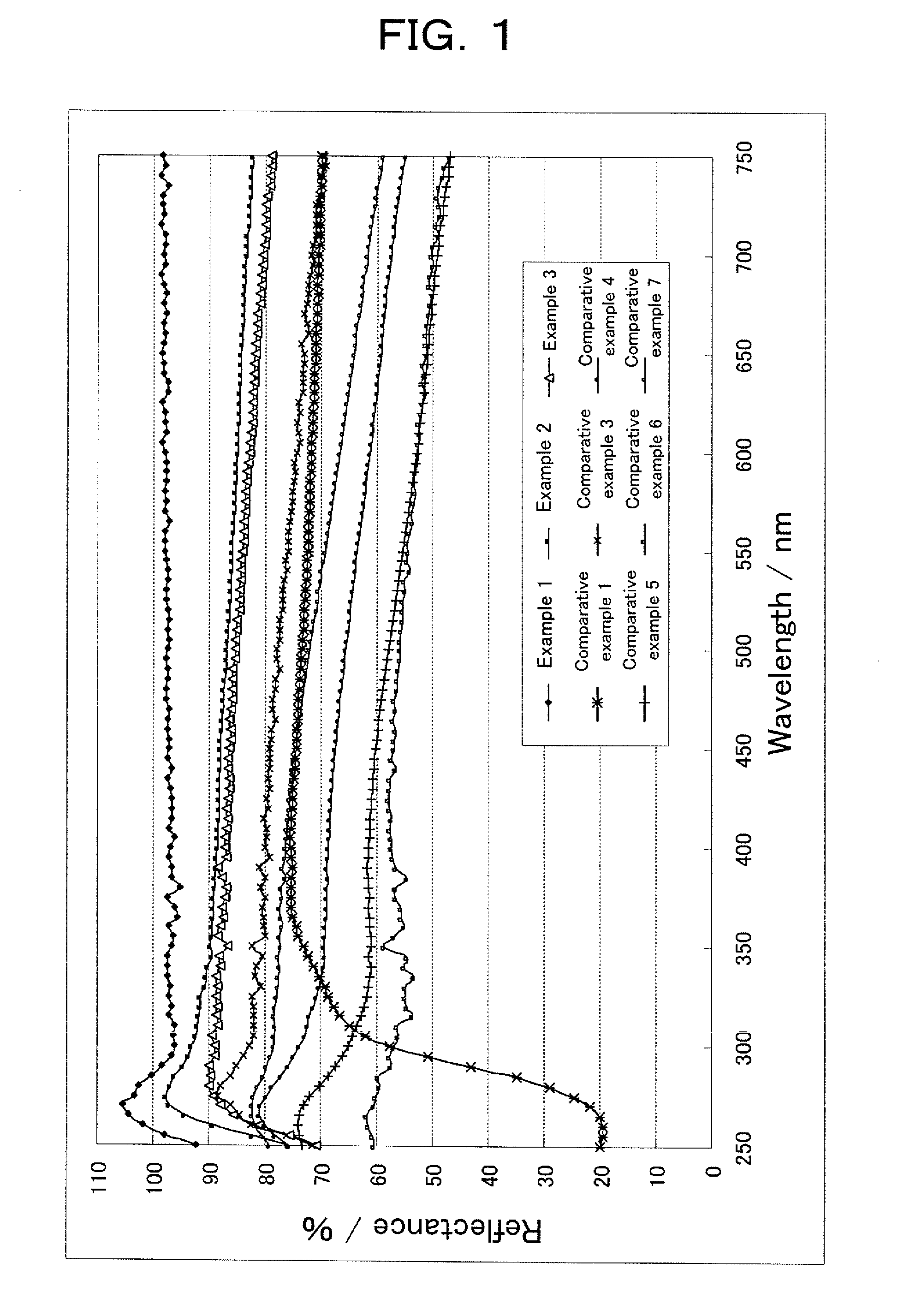
[0116]The measurement result of reflectance is shown in Table 1 and FIG. 1. As seen from these, reflectance in all wavelength in the range of 250˜750 nm was 90% or more. When this sintered body w...

Example

Comparative Example 1

[0118]Reflectance about 99.5% aluminum oxide (Al2O3) board fabricated by CoorsTek, Inc. was measured. The result is shown in Table 1 and FIG. 1. Also, the cross-section was measured by SEM, voids were not substantially observed.


PUM

PropertyMeasurementUnit
Temperatureaaaaaaaaaa

Abstract

A sintered ceramics for mounting a light-emitting element, which is capable of realizing high optical reflectance over the entire region from ultraviolet radiation to visible light. The sintered ceramics has a light-reflective face of which reflectance to light in each wavelength in the range of 250 nm˜750 nm is 70% or more. The light-reflective face satisfies following reaction:
|RA−RB|≦20
when reflectance to light of 750 nm is defined as RA%, and reflectance to light of 300 nm is defined as RB. The sintered ceramics has not layer to be peeled from the light-reflective face when a Tape Peeling Test is carried out to the light-reflective face in accordance with the method described in JIS H8504 (1990).

Description

TECHNICAL FIELD[0001]The present invention relates to a new sintered ceramics for mounting light-emitting element. More specifically, it relates to a sintered ceramics for mounting light-emitting element, which has excellent optical reflectance and is used for mounting light-emitting element, particularly light-emitting diode (hereinafter, refer to as “LED”.), and so on.BACKGROUND ART[0002]In recent years, development of light-emitting element like LED not only covers monochromatic LEDs emitting in red, green, blue and so on, but also reaches commercialization of white LED which can be obtained by applying fluorescent material to blue LED. Further, as the brightness of these LEDs is improved, these LEDs become frequently used for such as light source of electronic billboards, cell phones, and back-light source of computers.[0003]Blue LED, in general, uses GaN series compound semiconductor. The manufacturing method thereof is: firstly, generally, preparing insulating sapphire as a su...

Claims


Application Information

Patent Timeline
IPC IPC(8): C04B35/00B32B3/00H01L33/48H01L33/60
CPCC04B35/111C04B35/581C04B41/009C04B41/5031H01L2924/0002C04B2111/80H01L33/486H01L33/60Y10T428/24479C04B41/87C04B41/0072C04B41/4556H01L2924/00
Inventor SUGAWARA, KENMINABE, YUICHIROYONEDA, TAKEHIKOARIYUKI, MASAO
Owner TOKUYAMA CORP
Why Eureka
Try Eureka