Power Transmission Apparatus

a transmission apparatus and transmission line technology, applied in the direction of gearing, hoisting equipment, couplings, etc., can solve the problems of increasing the cost of cutting the gear teeth, and reducing the service life of the machin

Inactive Publication Date: 2008-11-13
KOREA T & B
View PDF5 Cites 2 Cited by
  • Summary
  • Abstract
  • Description
  • Claims
  • Application Information

AI Technical Summary

Problems solved by technology

However, because the teeth grooves 14 of the crown gear 4 were big in contacting area with the roller teeth 16 of the roller gear 6, it is probable that the power consumption due to the friction would still be big, and big and sharp noises would occur.
Especially, because the gear teeth 12 of the crown gear 4 should be machined to be inclined from the disk portion 10 by a predetermined angle, there occurs a problem that the cost is increased to machine the gear teeth by cutting while ensuring proper st

Method used


Image

  • Power Transmission Apparatus
  • Power Transmission Apparatus
  • Power Transmission Apparatus

Examples


Embodiment Construction

[0013]Hereinafter, the present invention will be explained in detail with reference to the appended drawings below.

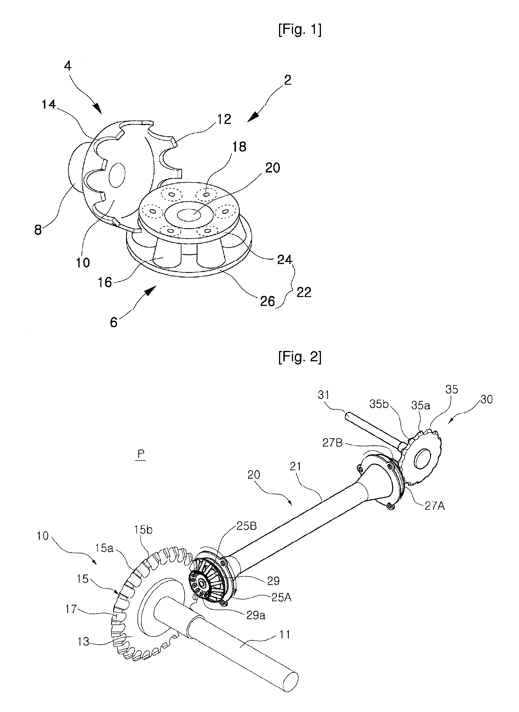
[0014]FIG. 1 is a perspective view showing FIG. 1 of the conventional art disclosed in the publication of the Korea patent registration No. 0414889,

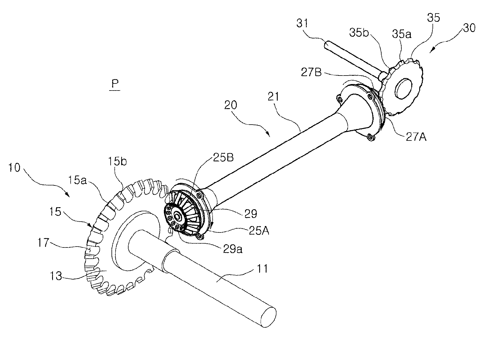
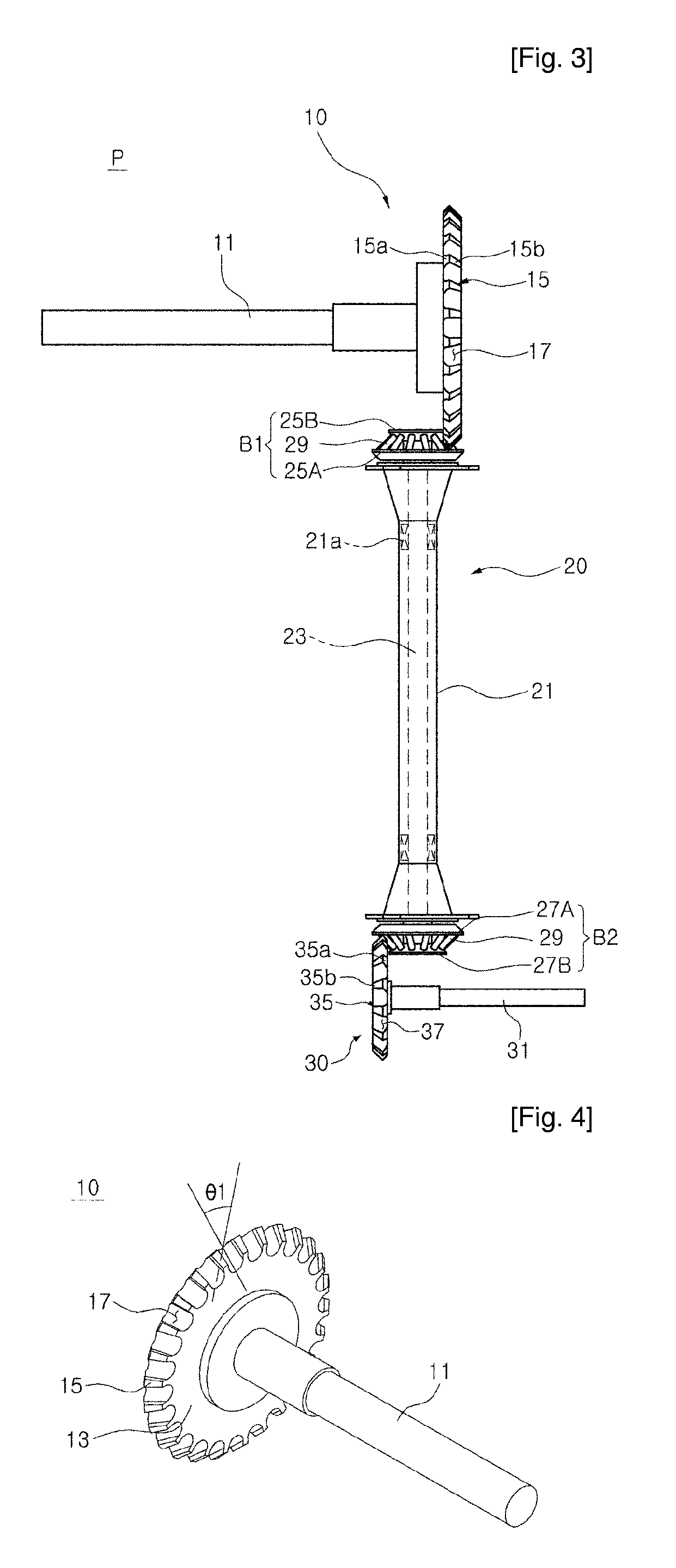
[0015]FIGS. 2 and 3 are an engagement perspective view and a plan view showing a power transmission apparatus according to the present invention,

[0016]FIG. 4 is a perspective view of a first gear of the power transmission apparatus according to the present invention,

[0017]FIG. 5 is a perspective view of the mediation member in the power transmission apparatus of the present invention.

[0018]For reference, the reference numerals of FIG. 1 related to the Korea patent registration No. 0414889 and the reference numerals shown in FIGS. 2 through 5 of the present invention are different from those shown in FIG. 1.

[0019]In the following description of the present invention, it is to be understood that the present invention will be d...


PUM


Abstract

The present invention relates to a power transmission apparatus having a high efficiency, which can cany out the rolling friction by constructing a cross shaft gear comprising a plurality of teeth formed with teeth grooves inclined to a desired angle, and a roller type mediation member having a plurality of rotation teeth engaged with the teeth grooves of the gear to thereby prevent the loss of the power and ensure the reliability of the operation and make it easy to fabricate, so as to embody the chainless power transmission for a bicycle. The power transmission apparatus of the present invention comprises a first gear having a first rotation shaft, a disk body installed at the first rotation shaft, a plurality of teeth arranged at a periphery of the disk body in the radial direction, and a plurality of teeth grooves, each of which is formed between the teeth and is arranged to define an acute angle relative to a virtual plane formed by the disk body; a mediation member having two rotation bodies spaced apart from each other, and a plurality of rotation teeth rotatably secured between the two rotation bodies by means of shaft pins so as to be engaged with the teeth grooves of the first gear, and in which an axial line of the pair of rotation bodies is arranged to define an acute angle relative to an axial line of the rotation tooth; and wherein the first gear and the mediation member define a cross shaft gear.

Description

TECHNICAL FIELD[0001]The present invention relates to a power transmission apparatus constituting a cross shaft gear, and more particularly to a power transmission apparatus having a high efficiency, which makes it possible to carry out rolling friction by constructing the cross shaft gear comprising a plurality of gears formed with teeth grooves inclined to a desired angle, and a roller type mediation member having a plurality of rotation teeth engaged with the teeth grooves of the gear to thereby reduce the friction coefficient so that it is possible to prevent the loss of the power and ensure the reliability of the operation and make it easy to fabricate, so as to embody the chainless power transmission for a bicycle.BACKGROUND ART[0002]To realize a chainless bicycle, several conventional technologies have been developed such as disclosed in Korea patent application laid open No. 1995-0029129 (1995. Nov. 22) entitled with “A bicycle of a bevel gear driven shaft power transmission...

Claims


Application Information

Patent Timeline
IPC IPC(8): F16H61/26B62M1/36
CPCB62M17/00F16H1/14Y10T74/19642F16H55/10F16H1/24F16H1/12
Inventor BAEK, CHANG KUN
Owner KOREA T & B
Why Eureka
Try Eureka