
Method of Manufacturing Cam Shaft, Cam Shaft, and Cam Lobe Material Used in the Same

Inactive Publication Date: 2008-11-13
NIPPON PISTONRING CO LTD
View PDF7 Cites 22 Cited by
  • Summary
  • Abstract
  • Description
  • Claims
  • Application Information

AI Technical Summary

Benefits of technology

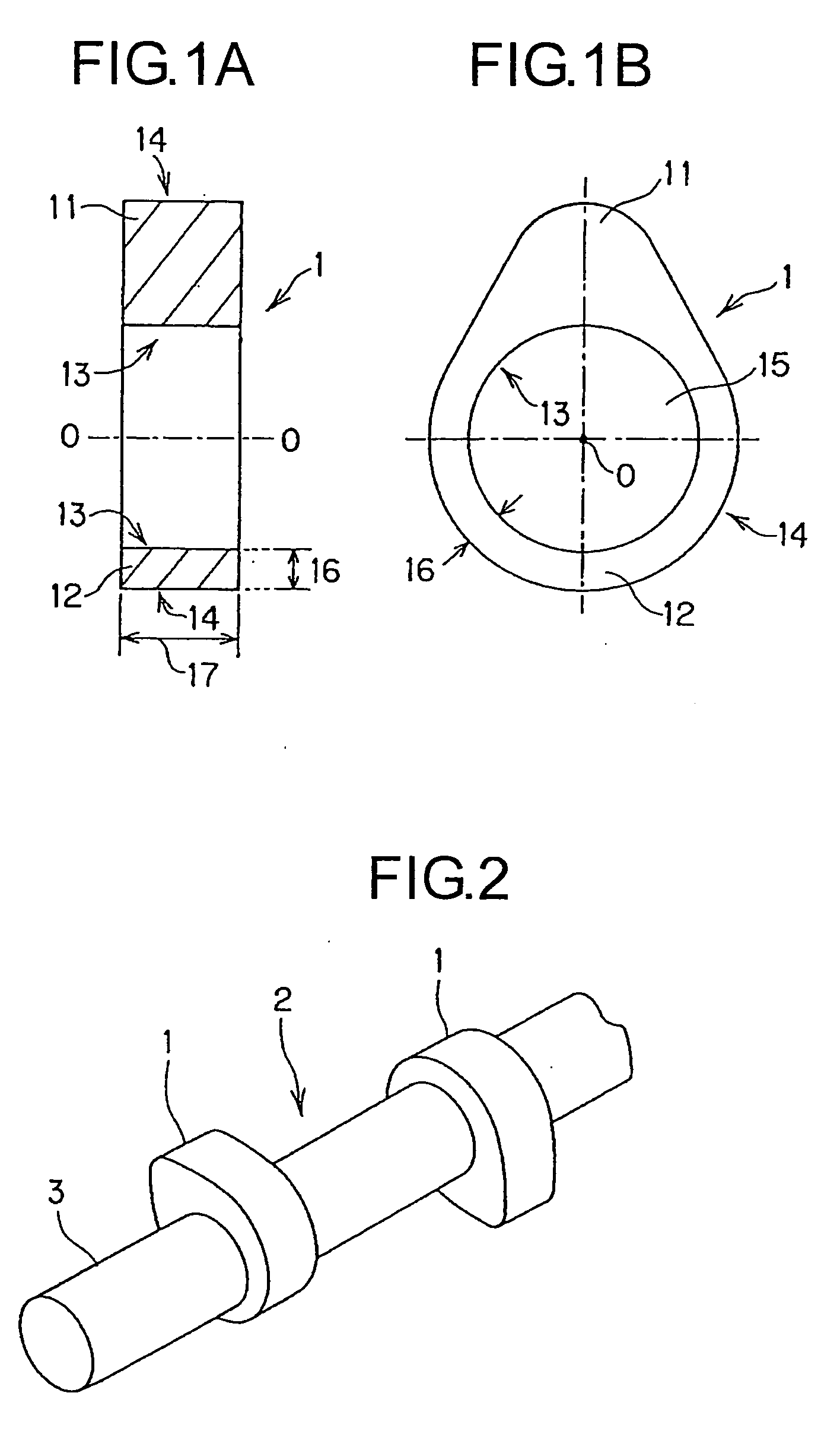
[0035]According to a method of manufacturing a cam shaft of the present invention, by subjecting an inner circumferential surface of a cam lobe to treatment for residual compressive stress addition treatment, it is possible to apply residual compressive stress to the treated surface. As a result of this, in the assembly that involves inserting a shaft onto the inner circumferential circle of the cam lobe, it is possible to expand the allowance of stress which the inner circumferential surface is capable of withstanding. As a result of this, cracks are less apt to be formed in the cam l

Problems solved by technology

The above-described chilled cam shaft had the problem that this shaft is inferior in pitting resistance although it has wear resistance and scuffing resistance.
As a result of this, in the same manner as in the case where the base wall thickness is decreased, cracks are generated in the cam lobe and a decrease in repeated contact fatigue strength occurs in the periphery of the cam lobe.

Method used


Image

  • Method of Manufacturing Cam Shaft, Cam Shaft, and Cam Lobe Material Used in the Same
  • Method of Manufacturing Cam Shaft, Cam Shaft, and Cam Lobe Material Used in the Same
  • Method of Manufacturing Cam Shaft, Cam Shaft, and Cam Lobe Material Used in the Same

Examples


example 1

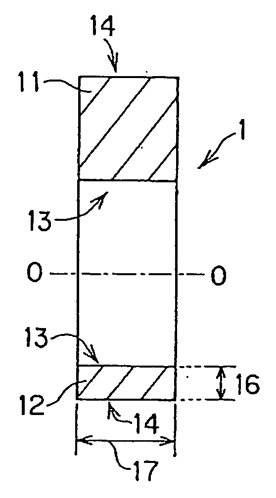
[0087]After secondary sintering, iron-based alloy powders consisting essentially of 0.8% by mass of C, 3.5% by mass of Ni, 0.3% by mass of Mo, and the balance Fe and incidental impurities were prepared, zinc stearate was added as a lubricant to the iron-based alloy powders, and they were mixed together. Next, the mixture was compression molded (primary molding) to the shape of the cam lobe 1 at a compressive load of 5 to 7 tons / cm2 and then temporarily sintered (primary sintering) at 600 to 900° C. in a vacuum sintering furnace. Furthermore, to the primary sintered body, compression molding (secondary molding) was performed at a compressive load of 7 to 10 tons / cm2 and regular sintering (secondary sintering) was then performed at 1100 to 1200° C. in the vacuum sintering furnace. Subsequently, this sintered body was subjected to quenching and tempering treatment (heating at 900° C. for 100 minutes, then oil quenching, further heating at 150° C. for 60 minutes, then air cooling), wher...

examples 2 to 5

[0089]Sintered bodies were fabricated in the same manner as with Example 1 from iron-based alloy powders to obtain the chemical compositions shown in Table 1 after secondary sintering, heat treatment similar to that of Example 1 was performed, and the cam lobe materials 1 of Examples 2 to 5 were obtained.

[0090]For each of the examples with a numeral “−1,” Examples 2-1, 3-1, 4-1 and 5-1, only the inner circumferential surface 13 of a cam lobe material was subjected to treatment for residual compressive stress addition treatment in the same manner as with Example 1-1, whereby the cam lobe material 1 was fabricated. Also, for each of the examples with a numeral “−2,” Examples 1-2, 2-2, 3-2, 4-2 and 5-2, both of the inner circumferential surface 13 and the outer peripheral surface 14 of a cam lobe material was subjected to treatment for residual compressive stress addition treatment, whereby the cam lobe material 1 was fabricated.


PUM

PropertyMeasurementUnit
Compressive stressaaaaaaaaaa
Degree of freedomaaaaaaaaaa
Compressive stressaaaaaaaaaa

Abstract

A method of manufacturing a cam shaft that prevents cracks during the joining of a cam lobe to a shaft, and improves the degree of freedom of design of the cam lobe is provided.By a method of manufacturing a cam shaft that after an inner circumferential surface 13 of a cam lobe 1 is subjected to treatment for residual compressive stress addition treatment, the cam lob 1 is joined to a shaft, above problem is solved. It is preferred that the residual compressive stress on the inner circumferential surface 13 of the cam lobe 1 is not less than 100 MPa. In addition, an outer peripheral surface 14 of the cam lobe 1 can be also subjected to treatment for residual compressive stress addition treatment. As the treatment for residual compressive stress addition treatment, shot-peening treatment, induction hardening treatment, barrel polishing treatment, carburizing and quenching treatment or carbonitriding treatment is performed.

Description

TECHNICAL FIELD[0001]The present invention relates to a method of manufacturing a cam shaft used in an internal combustion engine, a cam shaft, and a cam lobe material used in the cam shaft.BACKGROUND ART[0002]A cam shaft is used in a valve train of an internal combustion engine. In such an internal combustion engine, parts such as cam shaft and rocker arm slide at high speeds during operation and hence they are required to have sliding characteristics such as wear resistance, pitting resistance and scuffing resistance.[0003]For this reason, there has hitherto been used a cam shaft that is provided with a chilled cam in which a cam nose portion is rapidly cooled and caused to solidify during casting by using a chiller in this part, whereby a hard white cast iron structure is formed in the surface part of the cam nose. This chilled cam shaft, which has a hard chilled structure on its peripheral surface, has excellent wear resistance and scuffing resistance.[0004]On the other hand, in...

Claims


Application Information

Patent Timeline
IPC IPC(8): F01L1/047B23P15/00F16H53/02C21D9/30C21D1/10C21D7/06
CPCC21D1/10C21D7/06C21D9/30C22C38/08F01L1/047Y10T74/2101F01L2101/00F01L2103/00F01L2800/18F01L2820/01Y10T29/49293F01L1/16F01L2301/00F01L2303/00Y02P10/25B22F3/24F01L1/04F16H53/02
Inventor TAKAMURA, HIROYUKI
Owner NIPPON PISTONRING CO LTD
Learn More