Low-Power Fast Infrared Gas Sensor, Hand Held Gas Leak Detector, and Gas Monitor Utilizing Absorptive-Photo-Acoustic Detection

a technology of infrared gas sensor and detector, which is applied in the field of gas detection, can solve the problems of significant thermal mass, limiting the speed at which the detector can detect changes in incident energy, and detection speed and stability, and achieves the effects of low cost, low cost, and high-priced optical filters

Inactive Publication Date: 2008-11-13
CARDINALE DENNIS
View PDF17 Cites 70 Cited by
  • Summary
  • Abstract
  • Description
  • Claims
  • Application Information

AI Technical Summary

Benefits of technology

[0045]Low cost—the detector should have the lowest possible cost, i.e., high-priced optical filters should be eliminated (unlike Williams and prior-art PID / AID).

Problems solved by technology

For example, drawbacks specific to AID are detection speed and stability.
These devices generally have a significant thermal mass, thereby limiting the speed at which the detector can detect changes in incident energy.
In addition, as these devices primarily detect heat, and not infrared energy (heat is a secondary effect, generated by the absorption of infrared energy), they are susceptible to drift and noise caused by changes in ambient conditions (e.g., warm up, ambient temperature changes, mechanical vibrations, etc.).
Unfortunately, there are problems with the methods described above.
All this duplicity results in a final cost that is more than twice the cost of a single channel detector.
The chopping method, while greatly reducing drift, has its own drawbacks.
Therefore, expensive, unreliable mechanical choppers are sometimes used to increase the chopping speed.
Although there exist low-thermal-mass IR sources that can be operated at higher frequencies (up to 25 Hz or more), regardless of the chopping method employed, thermopile detectors are typically the limiting factor.
The synchronous amplifiers required to convert the AC signal back to a DC signal contribute their own problems.
First, they are susceptible to phase noise; signal drift due to phase changes of the electrical signal presented to the amplifier.
Phase noise occurs when analog component values change due to time or ambient condition changes.
This results in a very slowly changing output for fast changing input conditions.
Most obviously, cost is severely impacted—due to the use of electrically operated mechanical valves.
The power required to drive the valves is also an issue.
While this might be adequate for a monitoring-type system—where a device is looking for slow changes in gas concentration over long periods of time—it would not be acceptable for a leak detecting device—where rapid changes over short periods of time must be detected.
Calibrated gas samples are expensive, difficult to procure in remote locations and, many times, are hazardous (e.g., poisonous, explosive).
The main drawback of both technologies is the requirement for an optical filter(s) for band-limiting the infrared energy to the bands of interest for the gas(es) in question.
First, these filters are expensive.
In addition, even the best filter's pass-band spectrum cannot precisely match the absorption spectrum of the gas(es) in question, therefore degrading the selectivity and sensitivity of the detector.
Moreover, the pass-band spectra of such filters are subject to variations due to each of manufacturing processes, temperature, humidity, and age.
Additionally, both technologies require significant electrical power to operate.
Mechanical choppers used in AC designs, and valves used in photo-acoustic designs also consume significant power and, as mechanical devices, are inherently unreliable.
This detector does not utilize any method for stabilizing the resulting signal obtained from the detector (nor does the description disclose any such stabilization).
Thus, there is no possible way for the '993 device to quantify the concentration of gas(es)-of-interest within the sample chamber.
While detection of target gases results using the '993 device, the '993 invention is susceptible to frequent false indications due to rapidly changing environmental conditions, for example, to insufficient warm-up, to electrical noise, or to other ambient noise sources.
Significantly, operating an IR source at DC also seriously impacts the life of the IR source.
As an additional drawback, the '993 device requires manual user intervention in the form of a zero or null control, as evidenced by the 1 Hz / 2 Hz alarm function.
Nevertheless, the '873 design has significant problems.
Therefore, a great deal of power is needed to drive the bulb for adequate detection.
Second, the thermal time constant of the bulb is very long.
Therefore, the pulse rate has to stay at or below 1 Hz, resulting in slow detection.
Thus, significant low pass filtering is needed at the output of the sensor to recover the 1 Hz signal, resulting in an even slower response time.
Fourth, the sensor is physically large and cannot be adapted to a hand-held device (regardless of the noise problems that would cause).
Due to the large surface area of the components, it is difficult to contain the reference gas in the second chamber for long periods of time.

Method used


Image

  • Low-Power Fast Infrared Gas Sensor, Hand Held Gas Leak Detector, and Gas Monitor Utilizing Absorptive-Photo-Acoustic Detection
  • Low-Power Fast Infrared Gas Sensor, Hand Held Gas Leak Detector, and Gas Monitor Utilizing Absorptive-Photo-Acoustic Detection
  • Low-Power Fast Infrared Gas Sensor, Hand Held Gas Leak Detector, and Gas Monitor Utilizing Absorptive-Photo-Acoustic Detection

Examples


Embodiment Construction

[0100]As required, detailed embodiments of the present invention are disclosed herein; however, it is to be understood that the disclosed embodiments are merely exemplary of the invention, which can be embodied in various forms. Therefore, specific structural and functional details disclosed herein are not to be interpreted as limiting, but merely as a basis for the claims and as a representative basis for teaching one skilled in the art to variously employ the present invention in virtually any appropriately detailed structure. Further, the terms and phrases used herein are not intended to be limiting; but rather, to provide an understandable description of the invention.

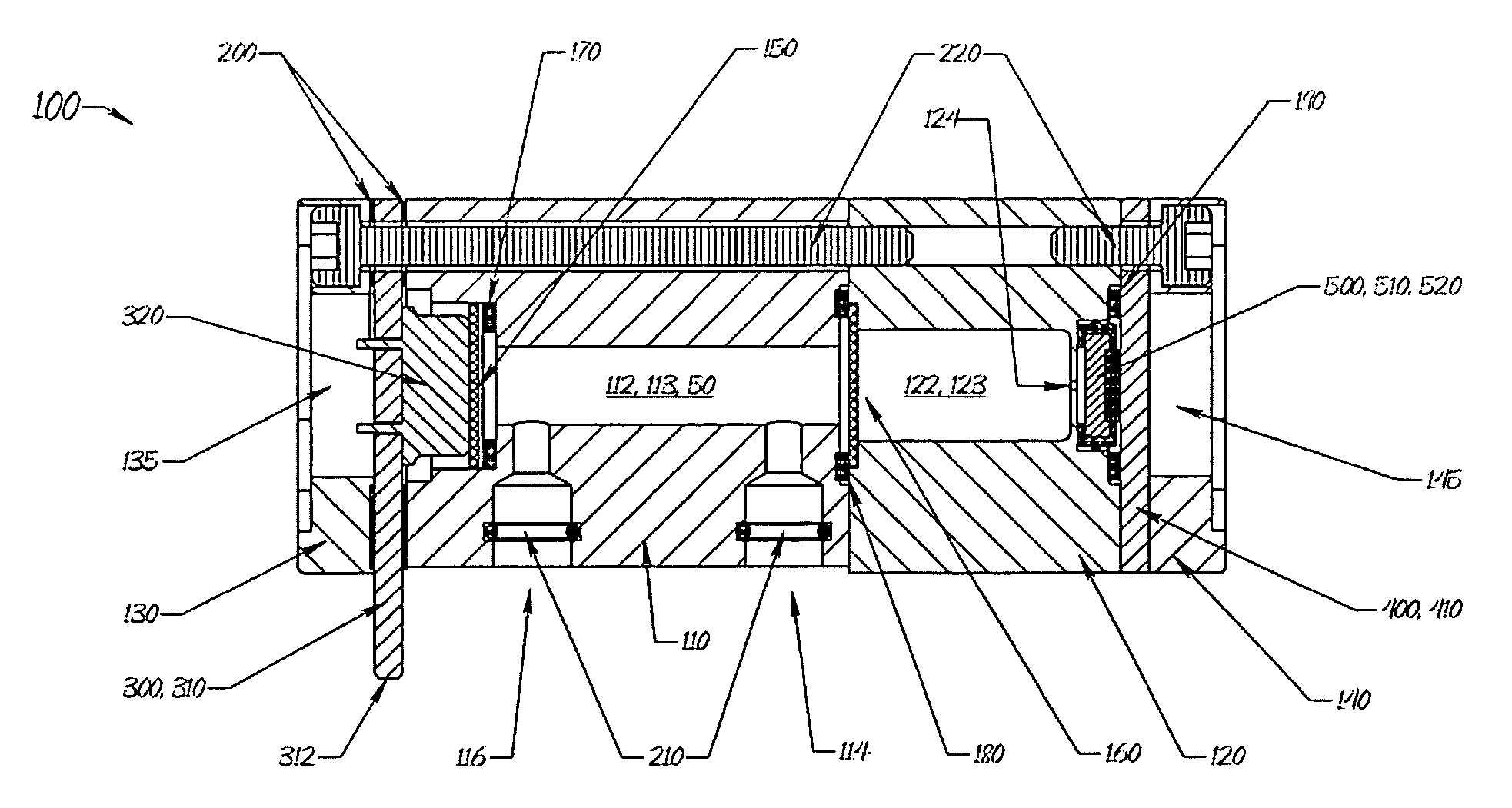
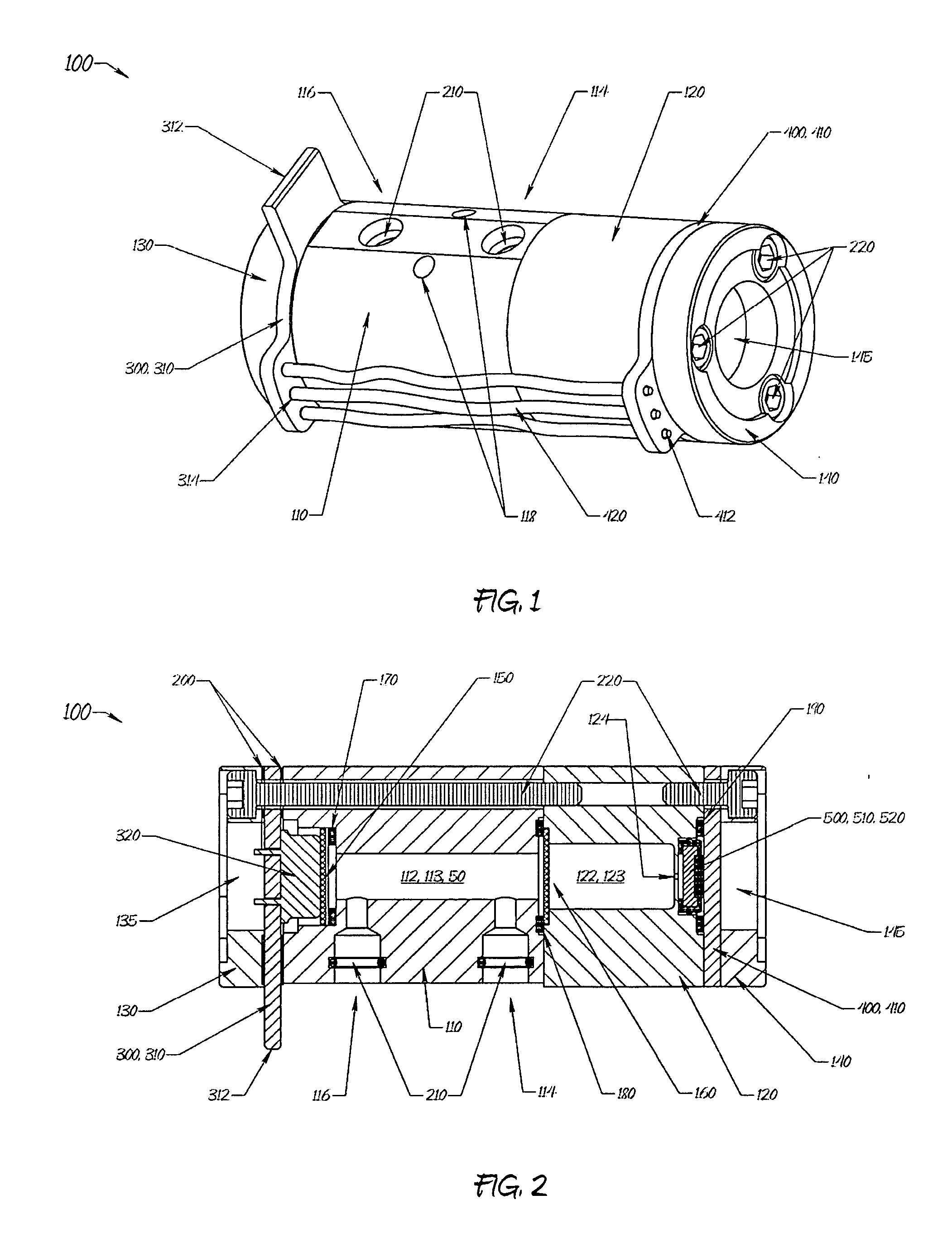
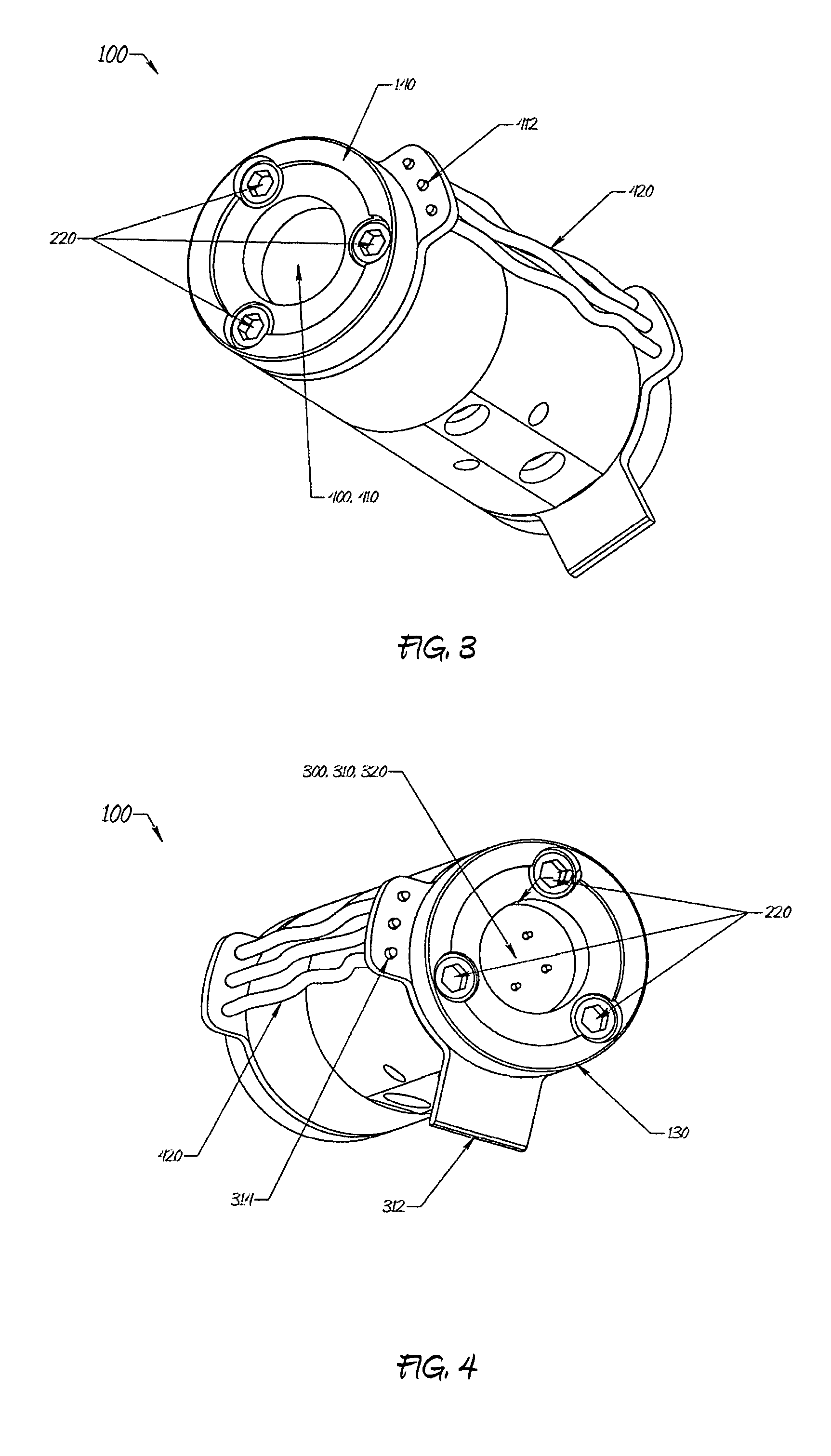
[0101]Embodiments herein can be implemented in a wide variety of ways using a variety of technologies that enable IR gas detection. Turning now to FIGS. 1 through 5, there is shown a sensor assembly 100 constructed of four machined components: a manifold 110, the reference body 120, and two end caps 130, 140. Each ...


PUM


Abstract

A gas sensor for sensing the presence of a gas includes an IR source, a microphone, a reference gas substantially similar to the gas to be detected, a reference body defining a reference chamber therein, the reference chamber having a pressure port coupled to the microphone, and a broad-band optical window through which at least IR wavelengths corresponding to absorption peaks of the predetermined gas may pass. The window is disposed between the IR source and reference chamber. The reference gas is contained within the reference chamber between the optical window and the microphone. The sensor can be included in a hand-held gas detection instrument having power supply, an outer shell, a circuit board assembly including sensor circuitry, a suction pump, actuation controls and status indicators. A probe defining a lumen therethrough supplies the sample gas.

Description

CROSS-REFERENCE TO RELATED APPLICATION[0001]This application claims the benefit under 35 U.S.C. § 119(e) of U.S. Provisional Application No. 60 / 928,000 filed May 7, 2007, the complete disclosure of which is hereby incorporated by reference herein in its entirety.BACKGROUND OF THE INVENTION[0002]1. Field of the Invention[0003]The invention lies in the field of gas detection based upon Non-dispersive Infrared Absorption (NDIR).[0004]2. Description of Related Art[0005]NDIR technology has existed for a number of years as a preferred method of gas detection. The technology depends on the fact that gases absorb infrared energy (light) at particular wavelengths, and different gases have peak absorption at different wavelengths. This absorption occurs according to the Beer-Lambert law:T=I1I0=-α·l[0006]where T is transmittance, I0 is the IR energy intensity (at a particular wavelength) presented to the gas sample, I1 is the IR energy intensity transmitted by the gas sample, α is the absorpti...

Claims


Application Information

Patent Timeline
Patent Type & Authority Applications(United States)
IPC IPC(8): G01J5/02
CPCG01M3/002G01M3/007G01M3/22G01M3/38G01N21/1702G01N21/3504G01N21/61
Inventor CARDINALE, DENNIS
Owner CARDINALE DENNIS
Why Eureka
Try Eureka