Lighting System Using Gps Receiver

a technology of gps receiver and light source, which is applied in the direction of identification means, instruments, heating types, etc., can solve the problems of inability to receive time signals from satellite radio, inability to accurately measure the x-tal oscillator used in the clock chip, and inability to accurately measure the x-tal oscillator, etc., to achieve the effect of reducing manufacturing costs, low cost and reducing the number of components

Inactive Publication Date: 2008-11-13
STWOL CO LTD
View PDF4 Cites 37 Cited by
  • Summary
  • Abstract
  • Description
  • Claims
  • Application Information

AI Technical Summary

Benefits of technology

[0024]A lighting system according to the present invention can reduce a manufacturing cost. In the lighting system, a GPS receiver itself receives GPS satellite signal, sunrise time and sunset time are automatically calculated from the received position information and reception information by using a baseband processor, and a security light is turned on/off at the calculated sunrise and sunset time. Accordingly, the number of components is greatly reduced.
[0025]Also, an artificial intelligent lighting s...

Problems solved by technology

However, when a dark current is generated or it is a cloudy day or a lot of dust accumulates in the photodiode, power may be dissipated and persons may complain.
However, an X-TAL oscillator used in the clock chip is not precise and is sensitive to environment and tempera...

Method used


Image

  • Lighting System Using Gps Receiver
  • Lighting System Using Gps Receiver
  • Lighting System Using Gps Receiver

Examples


Embodiment Construction

[0031]Hereinafter, a lighting system using a GPS receiver according to the present invention will be described in detail with reference to the accompanying drawings.

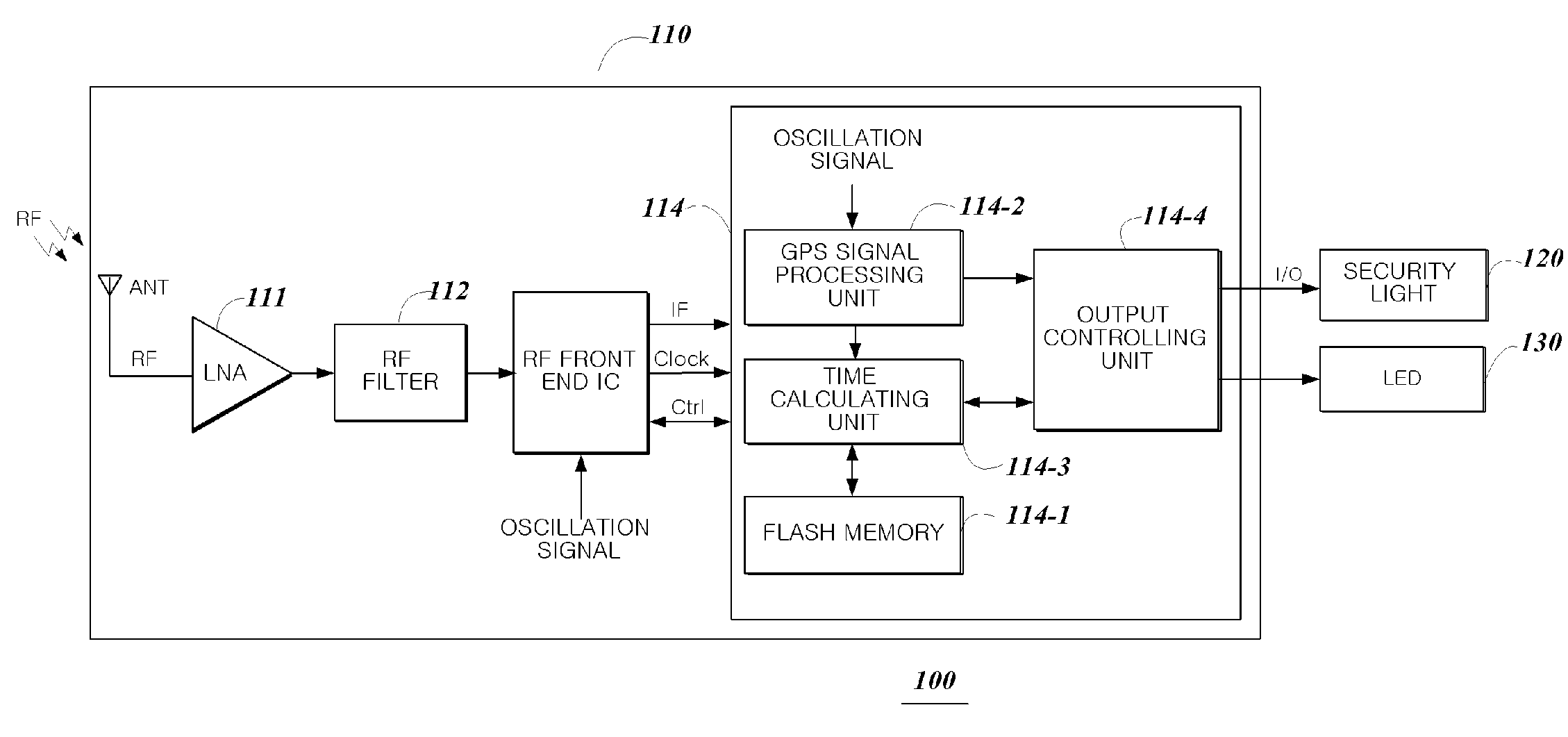
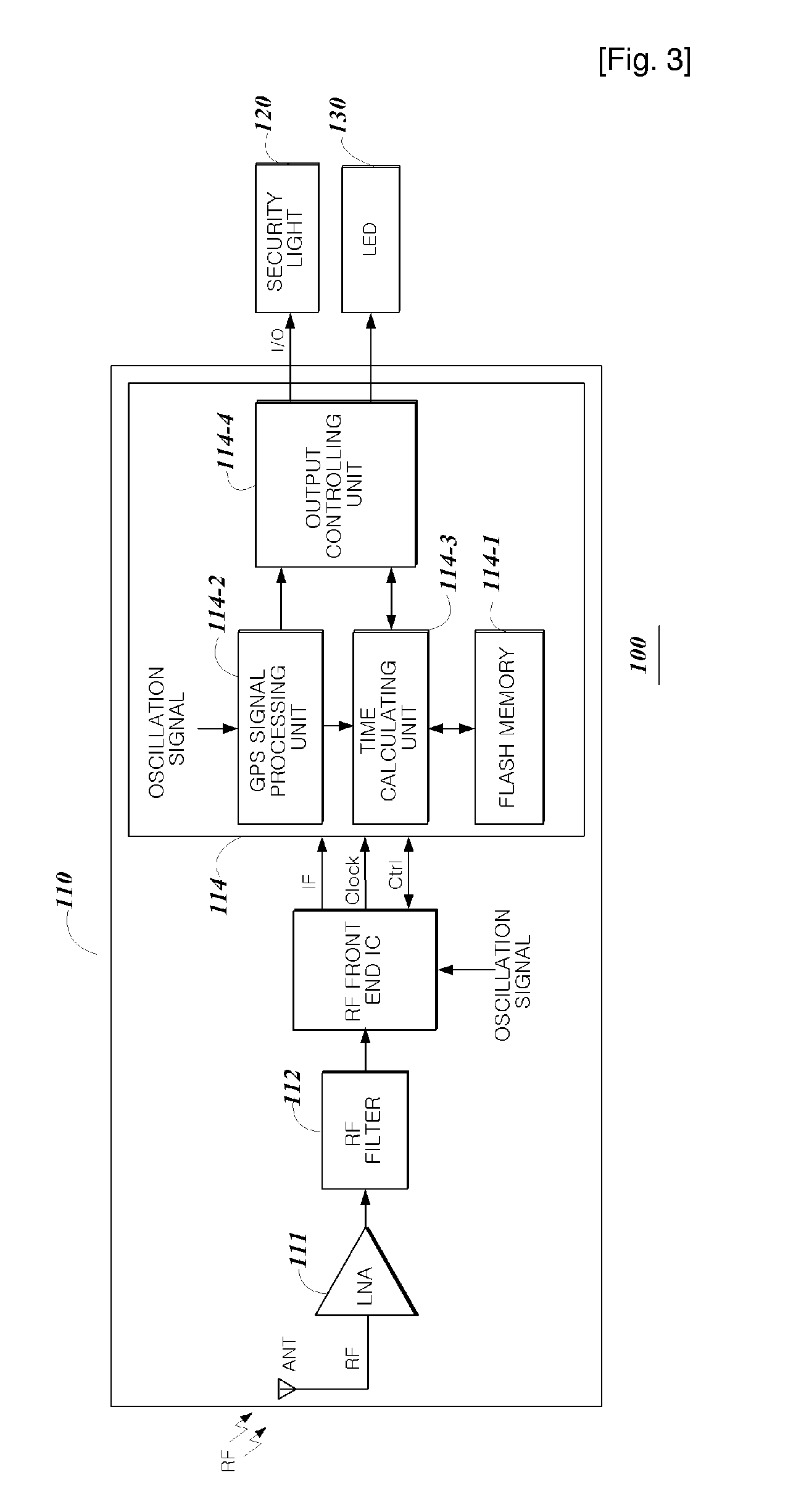
[0032]FIG. 3 is a block diagram of a lighting system using a GPS receiver according to an embodiment of the present invention.

[0033]Referring to FIG. 3, a lighting system 100 includes a GPS receiver 110, a security light 120, and an LED 130.

[0034]Also, the GPS receiver 110 includes an LNA 111, an RF filter 112, an RF front-end IC 113, and a baseband processor 114.

[0035]The LNA 111 amplifies an RF signal received from a GPS satellite through an antenna ANT.

[0036]The RF filter 112 filters the RF signal outputted from the LNA 111. A high pass filter, a band pass filter and a low pass filter can be used as the RF filter 112.

[0037]The RF front-end IC 113 converts an output signal of the RF filter 112 into an IF signal.

[0038]The baseband processor 114 includes a flash memory 114-1, a GPS signal processing unit 114-2, a time ca...


PUM


Abstract

A lighting system using a GPS receiver is provided. The lighting system includes: a GPS receiver for calculating sunrise time and sunset time from an inputted GPS signal and outputting an on/off signal and a satellite detection indicating signal according to the calculated sunrise time and sunset time; a security light configured to be turned on/off in response to the on/off signal; and an LED configured to be turned on/off in response to the satellite detection indicating signal. Accordingly, the GPS receiver itself receives GPS satellite signal, sunrise time and sunset time are automatically calculated from the received position information and reception information by using a baseband processor, and a security light is turned on/off at the calculated sunrise and sunset time, so that the number of components is greatly reduced.

Description

TECHNICAL FIELD[0001]The present invention relates to a lighting system using a GPS receiver, and more particularly, to a lighting system using GPS for turning on / off a security light according to sunrise time and sunset time, which are directly calculated in a baseband processor that receives information from GPS.BACKGROUND ART[0002]Security light is attached to electric poles located between buildings or alleys for the purpose of illumination and crime prevention. A flasher is installed in each security light.[0003]A photoelectric control method and an electric control method are widely used to control a flasher of a security light.[0004]The photoelectric control method uses a photodiode (photoelectric transformation device). The photoelectric control method uses a characteristic that a reverse current in P-N junction or contact between a rectifying metal and a semiconductor increases a photovoltaic effect due to illumination of light.[0005]However, when a dark current is generate...

Claims


Application Information

Patent Timeline
IPC IPC(8): H05B37/02G01S19/14H04B1/16
CPCH05B37/0281Y02B20/42H05B47/16Y02B20/40F24F1/022F24F7/08
Inventor HWANG, JUN-DONG
Owner STWOL CO LTD
Why Eureka
Try Eureka