

Electrowetting devices
- Summary
- Abstract
- Description
- Claims
- Application Information
AI Technical Summary
Benefits of technology
Problems solved by technology
Method used
Image

Examples
example 1
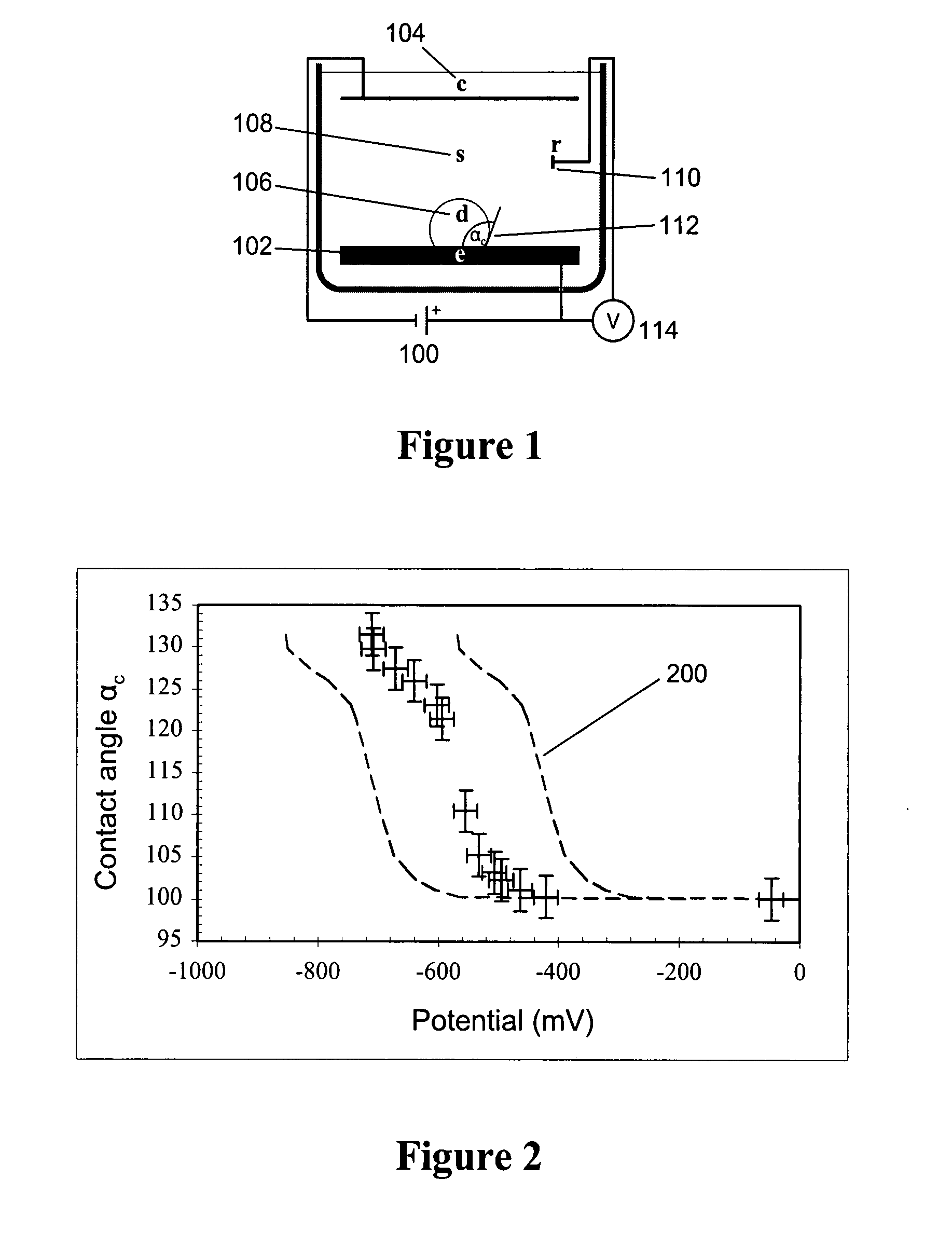
[0066]FIG. 1 illustrates a device that may be used to characterize contact-angle variation with voltage for an ITICL. The contact angle 112 of the liquid / liquid interface with the solid substrate is typically used to quantify interfacial shape. Voltage 100 is applied between planar working electrode 102 and a counterelectrode 104. Droplet 106 consists of a conductive liquid with volume ˜1 μL and the surrounding solution 108 is another, immiscible conductive liquid. 110 denotes a silver / silver chloride reference electrode, and the contact angle 112 of the droplet 106 on electrode 102 is labeled αc.
[0067]FIG. 2 shows the experimental data for an ITIES configured in the geometry shown in FIG. 1. For these experiments, the droplet 106 was composed of 0.01 mol / L TBA-TPB in 1,2-dichloroethane, and the surrounding solution 108 was composed of 0.5 mol / L lithium chloride. The working electrode 102 consisted of glass, on top of which was sputter-coated a chromium layer, which in turn was sput...
example 2
[0071]FIG. 5 illustrates the design of a device which may act as part of some focusing optics. The device has a transparent cover 1, which may be made of glass, and a transparent electrically conductive cover 4. The internal surface of the cover 4 is electrically conductive, thus enabling it to function as an electrode, and may for example be made of indium-doped tin oxide (ITO) covered glass. The side walls 12 of the device comprise an electrode 10, which may be made of nickel metal. The side walls 12 also include electrically-insulating seals 2, which may be made of a silicone elastomer, and by which the electrode 10 is attached to covers 1 and 4. Together, the side walls 12 and covers 1 and 4 form a chamber 14.
[0072]Inside the chamber 14 is a first solution 5, composed in this case of 0.5 mol / L lithium chloride, and a second solution 6, composed in this case of 0.01 mol / L TBA-TPB in 1,2-dichloroethane.
[0073]The passage of light through the device is indicated by arrow 8.
[0074]A p...
example 3
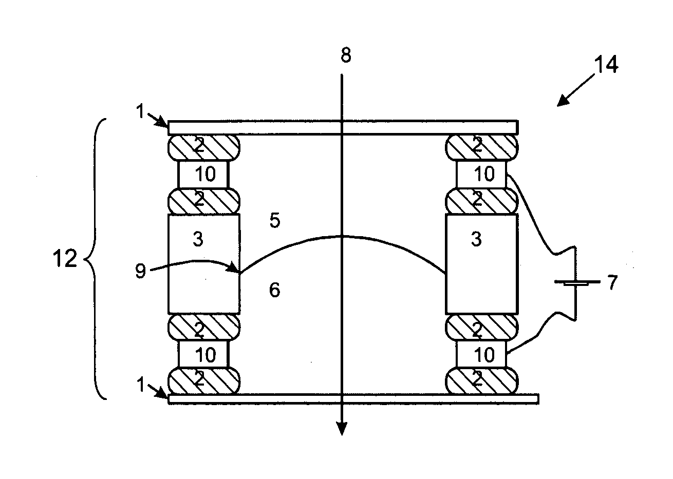
[0075]FIG. 6 illustrates another example of a device, similar to that of FIG. 5, but in this case employing two transparent electrically conducting covers 4, for example made of ITO glass (as described above), which function as electrodes. The side walls 12 incorporate a wall region 3 made of any suitable material, such as plastic. Electrically-insulating seals 2 are provided for attaching the wall region 3 to the covers 4. Together, the side walls 12 and covers 1 form a chamber 14.
[0076]As with Example 2, inside the chamber 14 is a first solution 5 (e.g. 0.5 mol / L lithium chloride) and a second solution 6 (e.g. 0.01 mol / L TBA-TPB in 1,2-dichloroethane). The three-phase contact line 9, between the two liquids 5 and 6, is present on the wall region 3. Thus, in this case, the three-phase contact line 9 is located between the two electrodes (4 and 4), and is not on either.
[0077]The passage of light through the device is again indicated by arrow 8.
[0078]In this example, the power supply...
PUM
| Property | Measurement | Unit |
|---|---|---|
| Electric potential / voltage | aaaaa | aaaaa |
| Electric potential / voltage | aaaaa | aaaaa |
| Frequency | aaaaa | aaaaa |
Abstract
Description
Claims
Application Information