Error driven RF power amplifier control with increased efficiency

a power amplifier and efficiency technology, applied in the direction of amplifier modification to reduce noise influence, gain control, supply voltage varying control, etc., can solve the problems of increasing the efficiency of pa 104, sacrificing power during the off-peak of amplitude, undesirable wide spectral occupancy, etc., to increase the efficiency of the power amplifier, and reduce the supply voltage

Active Publication Date: 2008-11-20
QUANTANCE
View PDF37 Cites 24 Cited by
  • Summary
  • Abstract
  • Description
  • Claims
  • Application Information

AI Technical Summary

Benefits of technology

[0019]In a second embodiment, the power amplifier controller includes a variable gain amplifier (VGA) coupled to the power amplifier for adjusting the amplitude of the RF input signal ahead of the power amplifier. The VGA is adjusted by a gain control signal based on the amplitude error signal; and thus, operates in a closed loop manner in which the VGA adjusts the input to the power amplifier to provide some correction for distortion at the RF output signal. This distortion correction allows the PA to operate closer to its saturation point; and thus, allows further decrease in a supply voltage to the PA compared to the first embodiment, thereby further increasing the PA's efficiency.
[0021]An advantage of the power amplifier controller according to the embodiments of the present invention is that it greatly increases the efficiency of the power amplifier by keeping the supply voltage of the power amplifier as low as possible while maintaining the distortion of the output signal near a predetermined level. Moreover, because the supply voltage of the power amplifier is adjusted according to the level of distortion in the output signal, the supply voltage can be accurately established, thus maximizing the overall efficiency of the power amplifier.

Problems solved by technology

RF PAs are one of the most significant sources of power consumption in these electronic devices, and their efficiency has a significant impact on the battery life of these portable electronic devices.
Since the RF spectrum is shared amongst users of the cellular telephone network, a wide spectral occupancy is undesirable.
This typically results in power being wasted during the off-peak of the amplitude of the RF input signal 106, as the biasing remains fixed for the acceptable distortion at the peak power level.
Certain RF modulation techniques have evolved to require even more spectral efficiency, and thereby forcing the PA 104 to sacrifice more efficiency.
However, the EER technique often fails to provide significant efficiency gains, because the supply voltage 108 cannot be varied in an energy-efficient way to accommodate the large variations in the amplitude signal of the RF input signal 106; and thus, it fails to provide a substantial energy efficiency gain while maintaining the required linear amplification of the RF signal in the PA 104.
This is mainly due to the difficulty in realizing a fast, accurate, wide range, and energy efficient voltage converter to drive the supply voltage of the PA 104.
This results in no change in the overall battery power being consumed by the RF transmitter because any efficiency gained in the PA 104 is mostly lost in the linear regulator itself.
Variations of the EER technique, such as Envelope Following and other various types of polar modulation methods, likewise fails to result in any significant gain in efficiency in the RF transmitter, because the supply voltage is likewise adjusted based on the amplitude signal of the RF input signal 106 which inherently has large variations; and thus, has the same deficiencies as described above with respect to conventional EER techniques.
However, the supply voltage 108 cannot be reduced too low, because this would cause the PA 104 to operate with insufficient voltage headroom, resulting in unacceptable distortion.
As described previously, the distortion may cause energy from the transmitted signal to spill over to adjacent channels, increasing spectral occupancy and causing interference to radios operating in those neighboring channels.
However, choosing a fixed power supply voltage is not sufficient in many applications.
This method does not yield an accurate estimate of the power of the RF output signal 110 because the estimated power may vary according to various operating conditions, such as temperature and frequency.
Therefore, even if the estimated power at some point approximates the actual power, changes in operating conditions result in deviation of the estimated power from the actual power.
Moreover, an estimate of the power of the RF output signal 110 may not be sufficient for properly adjusting the supply voltage 108.
Therefore, the conventional method of adjusting the supply voltage 108 of PA 104 based on an estimate of the PA output power is unsuitable in these cellular systems.
Further, the load presented to the PA 104 poses another problem.
The conventional methods described above, however, do not adjust the supply voltage in response to changes in the impedance of the circuitry.

Method used


Image

  • Error driven RF power amplifier control with increased efficiency
  • Error driven RF power amplifier control with increased efficiency
  • Error driven RF power amplifier control with increased efficiency

Examples


first embodiment

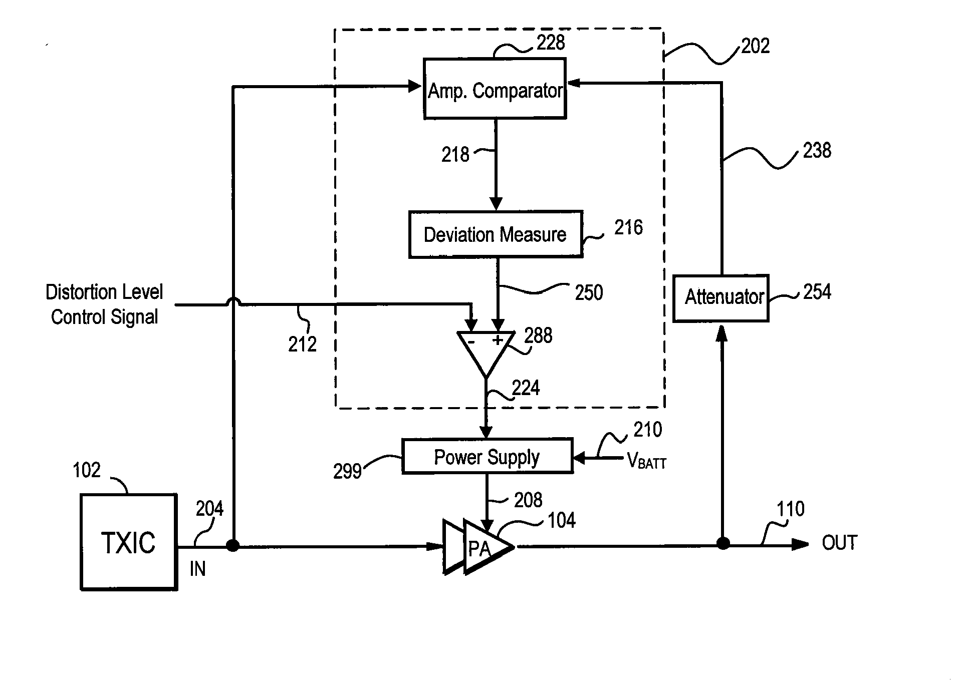
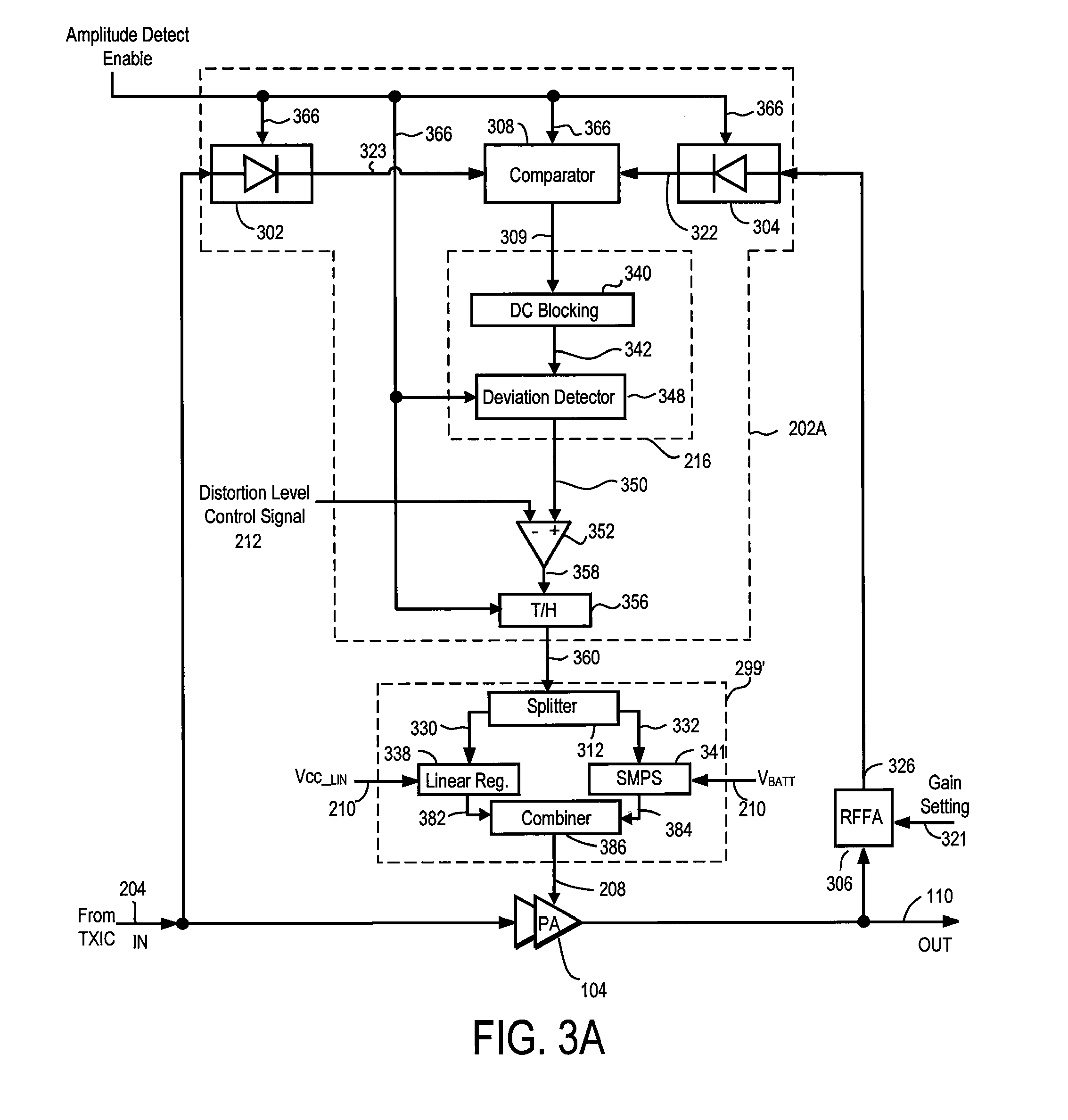
[0041]FIG. 3A illustrates an RF PA system, according to the present invention. The RF PA system includes, among other components, the PA 104, the PA controller 202A, an adjusted variable attenuator (RFFA (RF Feedback Attenuator)) 306, and a power supply 299′. The PA controller 381 includes, among other components, a comparator 308, a DC blocking module 340, a deviation detector 348, an error amplifier 352, a track and hold (T / H) module 356, and two matched amplitude detectors 302, 304. The power supply 299′ may include a splitter 312, a linear regulator 338, a switched-mode power supply (SMPS) 341, and a power combiner 386.

[0042]Referring to FIG. 3A, the amplitude of the RF input signal 204 is monitored through the amplitude detector 302 and compared by the comparator 308 with the amplitude of the RF input signal 110 as attenuated 326 by the adjusted variable attenuator (RFFA) 306, seen through a matched amplitude detector 304. Note that the amplitude detectors 302, 304 and the comp...

case 1

Case 1: Comparator 308 Generates Difference Between Amplitudes:

[0045]

cout(t)=s(t)−A*(s(t)+e(t))

case 2

Case 2: Comparator 308 Generates Difference Between Logarithms of Amplitudes:

[0046]cout(t)=log(A*(s(t)+e(t))-logs(t)=logA+log(s(t)+e(t))-logs(t)=logA+log(s(t)+e(t) / s(t))

where cout(t) is the amplitude error signal 309, s(t) is the RF input signal 204, A is the static ratio between the amplitudes of the RF input signal 204 and attenuated RF output signal 326 as detected by detectors 302, 304, and e(t) is the error added by the PA 104 to the RF input signal 204. If the RFFA 306 is adjusted accurately such that the RF output signal 110 of the PA 104 is attenuated to have an amplitude level corresponding to the amplitude level of the RF input signal 204, the value of A approaches 1. In Case 1, any deviation from A=1 affects the amplitude error signal 309 cout(t), thus requiring the RFFA 306 to be accurately adjusted to discern an accurate estimation of distortion by the deviation detector 348. In Case 2, the term log A, which is a DC (Direct Current) term, can be removed by a highpass fi...


PUM


Abstract

A power amplifier controller for adjusting a supply voltage to a power amplifier. The power amplifier controller adjusts the supply voltage so that distortion in an RF output signal corresponds to a predetermined limit. An amplitude error signal is generated by the power amplifier controller which represents a difference between an RF output signal and an attenuated RF output signal. The AC components of the amplitude error signal are processed to generate a deviation signal that represents the distortion in the RF output signal. The supply voltage to the power amplifier is increased when the deviation signal exceeds a distortion level control signal, and decreased when the deviation signal drops below the distortion level control signal.

Description

BACKGROUND OF THE INVENTION[0001]1. Field of the Invention[0002]The present invention relates to a circuit for controlling RF PAs (Radio Frequency Power Amplifiers), and more specifically, to an RF PA controller circuit that adjusts the supply voltage of RF PAs.[0003]2. Description of the Related Art[0004]RF (Radio Frequency) transmitters and RF power amplifiers are widely used in portable electronic devices such as cellular phones, laptop computers, and other electronic devices. RF transmitters and RF power amplifiers are used in these devices to amplify and transmit the RF signals remotely. RF PAs are one of the most significant sources of power consumption in these electronic devices, and their efficiency has a significant impact on the battery life of these portable electronic devices. For example, cellular telephone makers make great efforts to increase the efficiency of the RF PA systems, because the efficiency of the RF PAs is one of the most critical factors determining the ...

Claims


Application Information

Patent Timeline
Patent Type & Authority Applications(United States)
IPC IPC(8): H03G3/20
CPCH03F1/0222H03F1/34H03G3/004
Inventor DROGI, SERGE FRANCOISVINAYAK, VIKASTOMASZ, MARTIN
Owner QUANTANCE
Why Eureka
Try Eureka