
System and Method for Removing Particles From a Polishing Pad

a technology of polishing pad and particle removal, which is applied in the direction of grinding machine components, manufacturing tools, and abrasive surface conditioning devices, etc. it can solve the problems of undesirable build-up of particles on the polishing pad, localized differences in the polishing rate, and other abrasives may be used, so as to prolong the life improve the efficiency of material removal, and improve the efficiency and cleanliness of the polishing pad.

Active Publication Date: 2008-11-20
NXP USA INC +2
View PDF35 Cites 11 Cited by
  • Summary
  • Abstract
  • Description
  • Claims
  • Application Information

AI Technical Summary

Benefits of technology

[0016]In accordance with an aspect of the present invention there is provided a system and method for removing particles from a polishing pad to improve the efficiency of the removal of material by the polishing pad as part of a chemical-mechanical polishing process according to the accompanying claims.
[0017]This provides the advantage of improving the efficiency and cleanliness of a polishing pad and for extending the life of the polishing pad, thereby extending the time before a polishing pad requires to be changed. Additionally, by improving particle removal efficiency this will reduce defects in wafers polished by the polishing pad.

Problems solved by technology

However, other abrasives may be used.
However, by semiconductor fabrication standards CMP is inherently a dirty process, which in addition to a significant amount of foreign particles being introduced to the substrate surface also results in a significant amount of foreign particles, for example abrasive particles and by products of the planarization, being introduced to the polishing pad that can result in an undesirable built up of particles on the polishing pad, which is an effect known as ‘pad glazing’.
Additionally, the ‘glaze’ is often unevenly distributed over a polishing pad surface, which can result in localized differences in polishing rate and increased polishing non-uniformity.
Further, the foreign particles attached to the polishing pad can result in increased wafer defectivity such as scratches and particle residues.
One way to alleviate this problem has been via the use of deionised water being dispensed on the polishing pad to aid in the washing off of the foreign particles, however this technique is largely ineffective.
However, it has been found that the conditioning of a polishing pad with a conditioning disk typically results in the foreign particles being transferred to the conditioning disk and as a result a film builds up on the conditioning device and the conditioning capabilities of the conditioning disk are reduced resulting in a lower removal rate of unwanted particles from the polishing pad by the conditioning device and less uniform conditioning of the polishing pad by the conditioning device.

Method used


Image

  • System and Method for Removing Particles From a Polishing Pad
  • System and Method for Removing Particles From a Polishing Pad
  • System and Method for Removing Particles From a Polishing Pad

Examples


Embodiment Construction

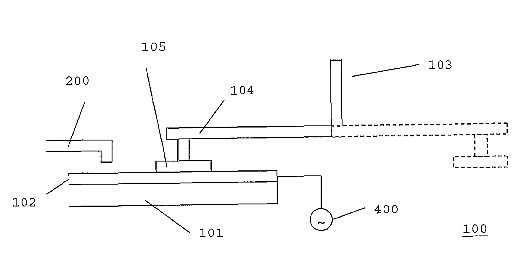
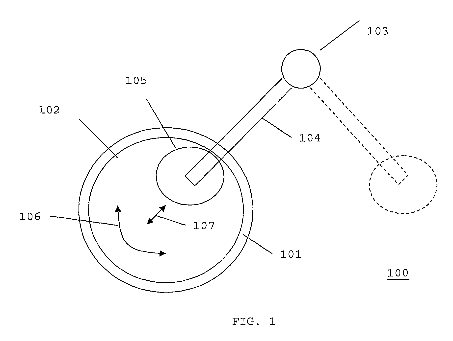
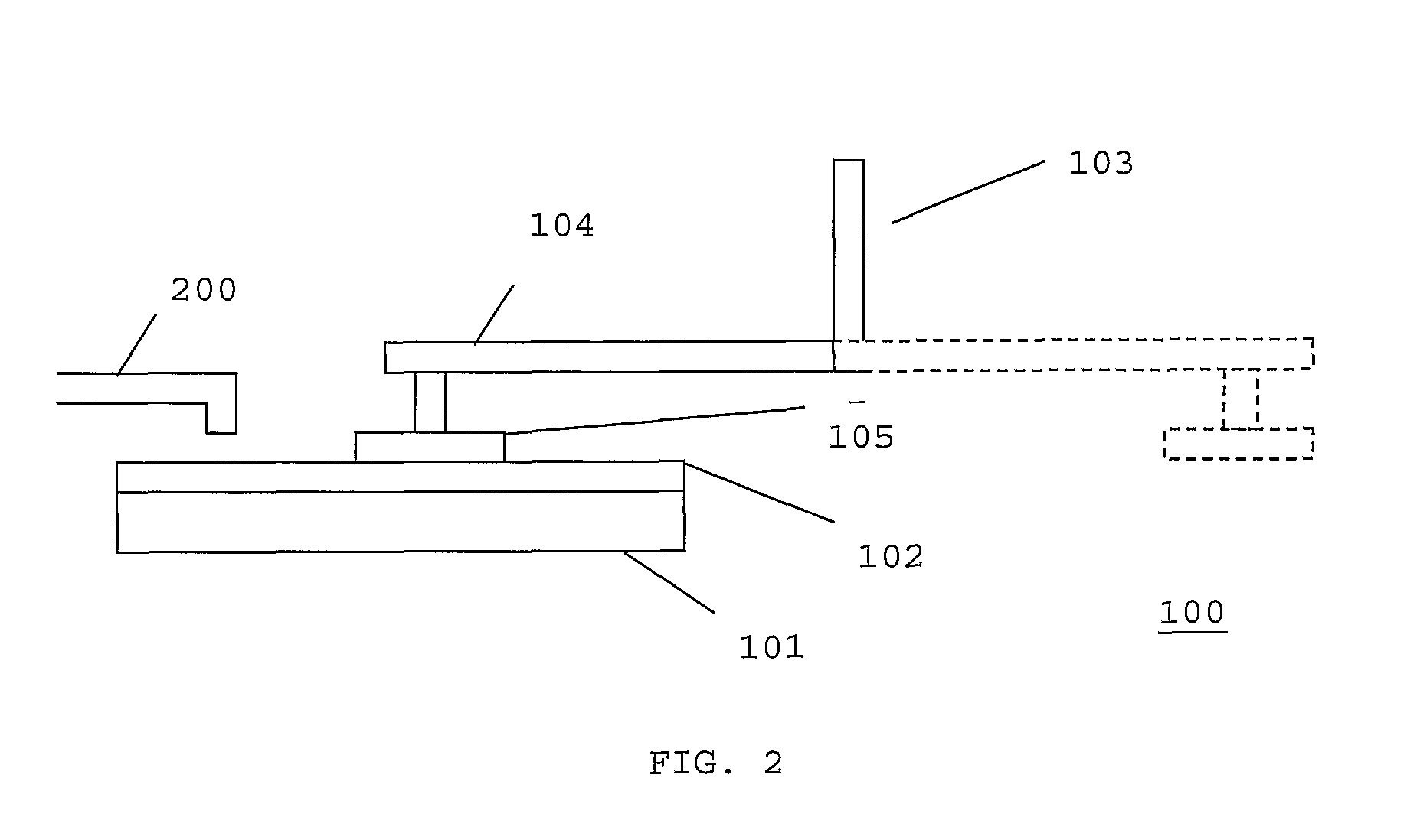
[0023]FIG. 1 illustrates a top plan of a polishing pad conditioning system 100 that may be used in a chemical-mechanical polishing process.

[0024]The polishing pad conditioning system 100 includes a platen 101. The platen 101 is arranged to rotate clockwise or counter-clockwise about a fixed or movable axis. A polishing pad 102 is attached to the platen 101 and as such is rotated by the platen 101. The polishing pad 102 is arranged to provide mechanical abrasion for removing a material layer from a substrate (not shown) during a chemical-mechanical polishing process, as is well known to a person skilled in the art.

[0025]The polishing pad conditioning system 100 further includes an optional conditioning device 103 having a conditioning arm 104 that is pivoted to allow the conditioning arm 104 to be disposed either away from the polishing pad 102, as shown by dotted line, or above the polishing pad 102. Attached to the conditioning arm 104, at the opposite end to the pivot, is a condit...


PUM

PropertyMeasurementUnit
frequencyaaaaaaaaaa
voltageaaaaaaaaaa
voltageaaaaaaaaaa

Abstract

A system for removing particles from a polishing pad to improve the efficiency of the removal of material by the polishing pad as part of a chemical-mechanical polishing process, the system comprising a polishing pad; a fluid dispenser arranged to dispense a fluid on the polishing pad; and removal means, wherein the removal means include a heater for increasing the temperature of the fluid dispensed on the polishing pad, and / or voltage means for coupling the polishing pad to a voltage source for repelling charged particles from the polishing pad surface while the fluid dispenser is dispensing the fluid on the polishing pad.

Description

FIELD OF THE INVENTION[0001]The present invention relates to system and method for removing particles from a polishing pad to improve the efficiency of the removal of material by the polishing pad as part of a chemical-mechanical polishing process.BACKGROUND OF THE INVENTION[0002]Modern integrated circuit IC devices typically employ shallow trench isolation and multi-level interconnects to meet the demands for increased functionality and faster processing speeds. However, planarization of interlevel dielectrics, conductive layers and trench dielectrics are required when using these technologies to obtain optimum fabrication results.[0003]One technique that provides planarization and has received widespread acceptance in the semiconductor processing industry is chemical-mechanical polishing CMP.[0004]CMP is used to planarize and remove surface topography irregularities of a material layer through chemical reaction and mechanical abrasion.[0005]Typically a CMP process involves placing...

Claims


Application Information

Patent Timeline
Patent Type & Authority Applications(United States)
IPC IPC(8): B24B7/00B24B53/017
CPCB23H5/08B24B53/001B24B53/017C25F1/00
Inventor KORDIC, SRDJANPETITDIDIER, SEBASTIENFARKAS, JANOSDEL MONACO, SILVIO
Owner NXP USA INC
Learn More