Phase-shifting element and particle beam device having a phase-shifting element

a technology of phase-shifting elements and particle beams, which is applied in the field of phase-shifting elements and particle beam devices having phase-shifting elements, can solve the problems of long time-consuming and laborious, carbon film is rapidly contaminated, and small holes are easily blocked, and achieves the effect of convenient manufactur

Inactive Publication Date: 2008-12-04
CARL ZEISS MICROSCOPY GMBH +1
View PDF20 Cites 35 Cited by
  • Summary
  • Abstract
  • Description
  • Claims
  • Application Information

AI Technical Summary

Benefits of technology

[0032]The particle beam device according to the system described herein has, in addition to the above-mentioned advantages, the advantage that the back focal plane and thus the diffraction plane of the objective is imaged enlarged in the intermediate diffraction pattern plane. Accordingly, the phase-shifting element may be designed similarly enlarged, so that the phase-shifting element is more easily manufacturable due to the not very strict dimensional requirements. It is furthermore advantageous that the second diffraction lens is situated in or in the area of the intermediate diffraction pattern plane, so that the second diffraction lens has an influence, in principle, virtually only on the position of an image plane conjugated with respect to an object plane of the objective.
[0033]The enlarged image of the diffraction plane is basically linearly distorted due to the at least one multipole element. This is also known as an anamorphotic image. The enlarged image of the diffraction plane is of a different size in the directions of two mutually perpendicular axes. The ratio of the enlargement with respect to these two axes is known as aspect ratio. The aspect ratio influences and defines the dimensions of the phase-shifting element. For the system described herein, an aspect ratio in the range of 1:10 to 1:100 may be advantageous.

Problems solved by technology

The use of a method of this type in electron microscopy, in particular in transmission electron microscopy, has for long not been possible.
It is, however, disadvantageous here that only a spatial frequency-dependent phase shift is achieved via this procedure, so that the achieved phase contrast is also spatial frequency-dependent.
It has been found, however, that the carbon film is rapidly contaminated.
In particular the small hole is easily clogged.
Furthermore, it is disadvantageous that the carbon film is rapidly charged.
However, the Hilbert phase plate has the same disadvantages as the Zernike phase plate.
However, the known Boersch phase plate has the disadvantage that, in particular due to the support, partial beams are shadowed and prevented from contributing to the interference, so that information is lost.
The disadvantage of this known phase plate is, however, also that a partial area of the scattered electrodes is shadowed and therefore part of the image information must be reconstructed.

Method used


Image

  • Phase-shifting element and particle beam device having a phase-shifting element
  • Phase-shifting element and particle beam device having a phase-shifting element
  • Phase-shifting element and particle beam device having a phase-shifting element

Examples


Embodiment Construction

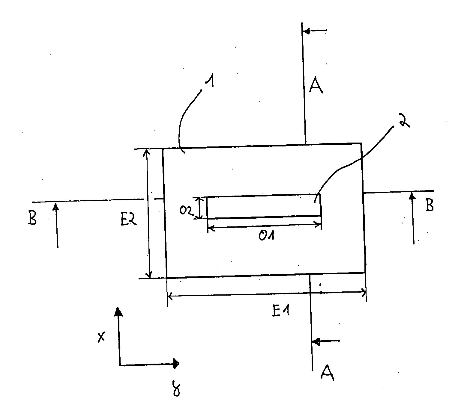
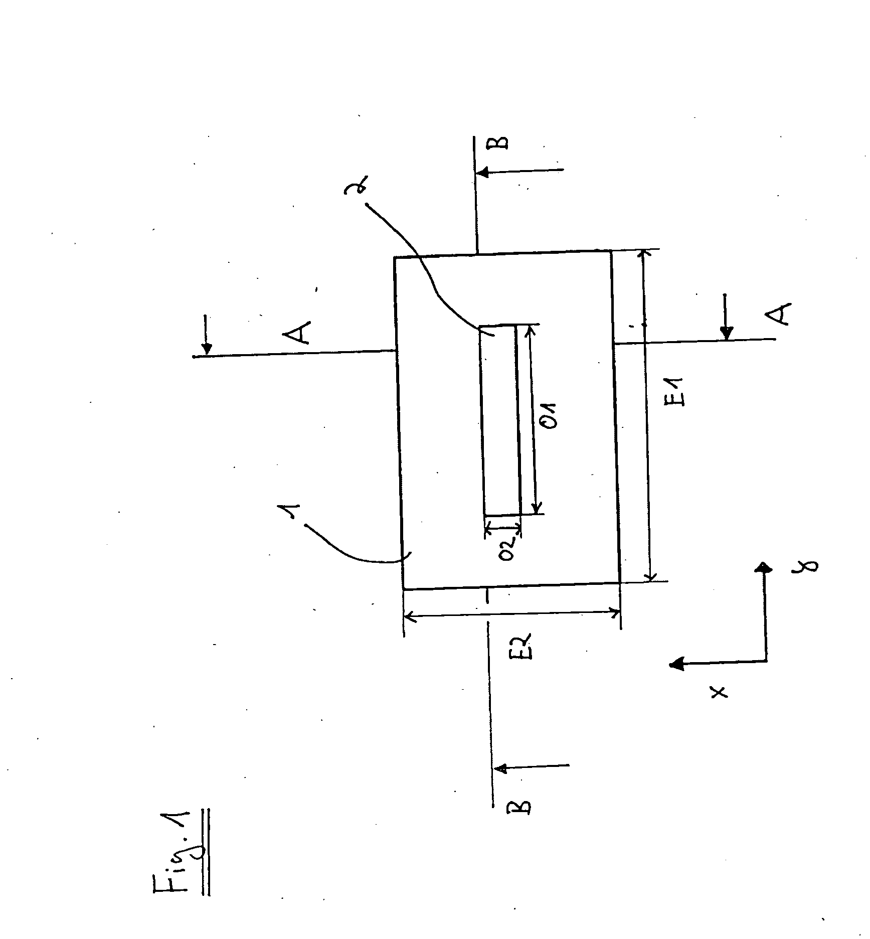
[0065]The system described herein is based on the recognition that a desired phase shift is achievable using simple geometric designs with the help of a non-homogeneous and / or anisotropic potential, in particular a non-homogeneous electric potential. FIG. 1 shows a top view of a first exemplary embodiment of a phase-shifting element 1 in the form of a phase plate in which a non-homogeneous potential or an anisotropic potential is generated. Phase-shifting element 1 is situated in the beam path of a particle beam device (for example, an electron beam device in the form of a TEM) in such a way that the optical axis of the particle beam device runs in the z direction, which is perpendicular to the plane of the page on which FIG. 1 is printed.

[0066]Phase-shifting element 1 has a first dimension E1 in the y direction and a second dimension E2 in the x direction. In principle, the phase plate has a rectangular design in this exemplary embodiment. It should be expressly pointed out that th...


PUM


Abstract

A phase-shifting element for shifting a phase of at least a portion of a particle beam is described, as well as a particle beam device having a phase-shifting element of this type. In the phase-shifting element and the particle beam device having a phase-shifting element, components shadowing the particle beam are avoided, so that proper information content is achieved and in which the phase contrast is essentially spatial frequency-independent. The phase-shifting element may have at least one means for generating a non-homogeneous or anisotropic potential. The particle beam device according to the system described herein may be provided with the phase-shifting element.

Description

TECHNICAL FIELD[0001]This application relates to a phase-shifting element for shifting a phase of at least a portion of a particle beam, as well as a particle beam device having a phase-shifting element of this type.BACKGROUND OF THE INVENTION[0002]The study of biological samples with the aid of a phase contrast has long been known in light microscopy. Using a so-called phase ring, which is situated in the back focal plane of a light microscope's objective, the radiation coming from a sample to be studied, which contains diffracted and undiffracted components, becomes phase-shifted by 90° (i.e., by π / 2) in the zeroth order of diffraction. The interference of the higher orders of diffraction with the phase-shifted beam delivers a contrast-rich image (image having a phase contrast).[0003]The use of a method of this type in electron microscopy, in particular in transmission electron microscopy, has for long not been possible. However, even in that case the use of a phase contrast study...

Claims


Application Information

Patent Timeline
Patent Type & Authority Applications(United States)
IPC IPC(8): H01J3/14
CPCH01J37/26H01J37/295H01J2237/041H01J2237/0453H01J2237/1534H01J2237/2455H01J2237/2614H01J2237/2802H01J2237/2809
Inventor SCHRODER, RASMUSBARTON, BASTIANBENNER, GERDROSE, HARALD
Owner CARL ZEISS MICROSCOPY GMBH
Why Eureka
Try Eureka