Borehole Conductivity Simulator Verification and Transverse Antenna Balancing

a conductivity simulator and borehole technology, applied in the field of borehole conductivity simulator verification and transverse antenna balancing, oil exploration, can solve the problems of not providing a measure of vertical conductivity or anisotropy, cannot be detected individually, and difficult to detect hydrocarbon-bearing zones, so as to reduce the effect of magnetic field

Active Publication Date: 2008-12-04
BAKER HUGHES INC
View PDF40 Cites 3 Cited by
  • Summary
  • Abstract
  • Description
  • Claims
  • Application Information

AI Technical Summary

Benefits of technology

[0026]Another embodiment of the disclosure is an apparatus for evaluating performance of the multicomponent induction logging tool having a plurality of transmitter antennas and a plurality of receiver antennas. The tool is positioned in a calibration area substantially free from components capable of interfering with magnetic and electric fields produced by the tool. The apparatus includes a borehole conductivity simulator having an impedance similar to that of a borehole environment, the borehole conductivity simulator coupling a first housing of the tool with a seco

Problems solved by technology

In general, when using a conventional induction logging tool with transmitters and receivers (induction antennas) oriented only along the borehole axis, the hydrocarbon-bearing zones are difficult to detect when they occur in multi-layered or laminated reservoirs.
These reservoirs usually consist of thin alternating layers of shale and sand and, oftentimes, the layers are so thin that due to the insufficient resolution of the conventional logging tool they cannot be detected individually.
Conventional induction logging devices, which tend to be sensitive only to the horizontal conductivity of the formations, do not provide a measure of vertical conductivity or of anisotropy.
One, if not the main, difficulties in interpreting the data acquired by a transversal induction logging tool is associated with vulnerability of its response to borehole conditions.
There are a few hardware margins and software limitations that impact a conventional transversal induction logging tool performance and result in errors appearing in the acquired data.
The general hardware problem is typically associated with an unavoidable electrical field that is irradiated by the tool induction transmitter simultaneously with the desirable magnetic field, and it happens in agreement with Maxwell's equations for the time varying field.
The transmitter electrical field interacts with remaining modules of the induction logging tool and with the formation; however, this interaction does not produce any useful information.
Indeed, due to the always-existing possibility for this field to be coupled directly into the receiver part of the sensor section through parasitic displacement currents, it introduces the noise.
When this coupling occurs, the electrical field develops undesirable electrical potentials at the input of the receiver signal conditioning, primarily across the induction antenna receiver, and this voltage becomes an additive noise component to the signal of interest introducing a systematic error to the measurements.
The problem could become even more severe if the induction logging tool operates in wells containing water-based fluids.
This circumstance apparently would result in a fact that capacitive coupling and associated systematic errors are environment dependant b

Method used


Image

  • Borehole Conductivity Simulator Verification and Transverse Antenna Balancing
  • Borehole Conductivity Simulator Verification and Transverse Antenna Balancing
  • Borehole Conductivity Simulator Verification and Transverse Antenna Balancing

Examples


Embodiment Construction

[0037]The instrument structure provided by the present disclosure enables increased stability and accuracy in an induction wellbore logging tool and its operational capabilities, which, in turn, results in better quality and utility of wellbore data acquired during logging. The features of the present disclosure are applicable to improve the structure of a majority of known induction tools.

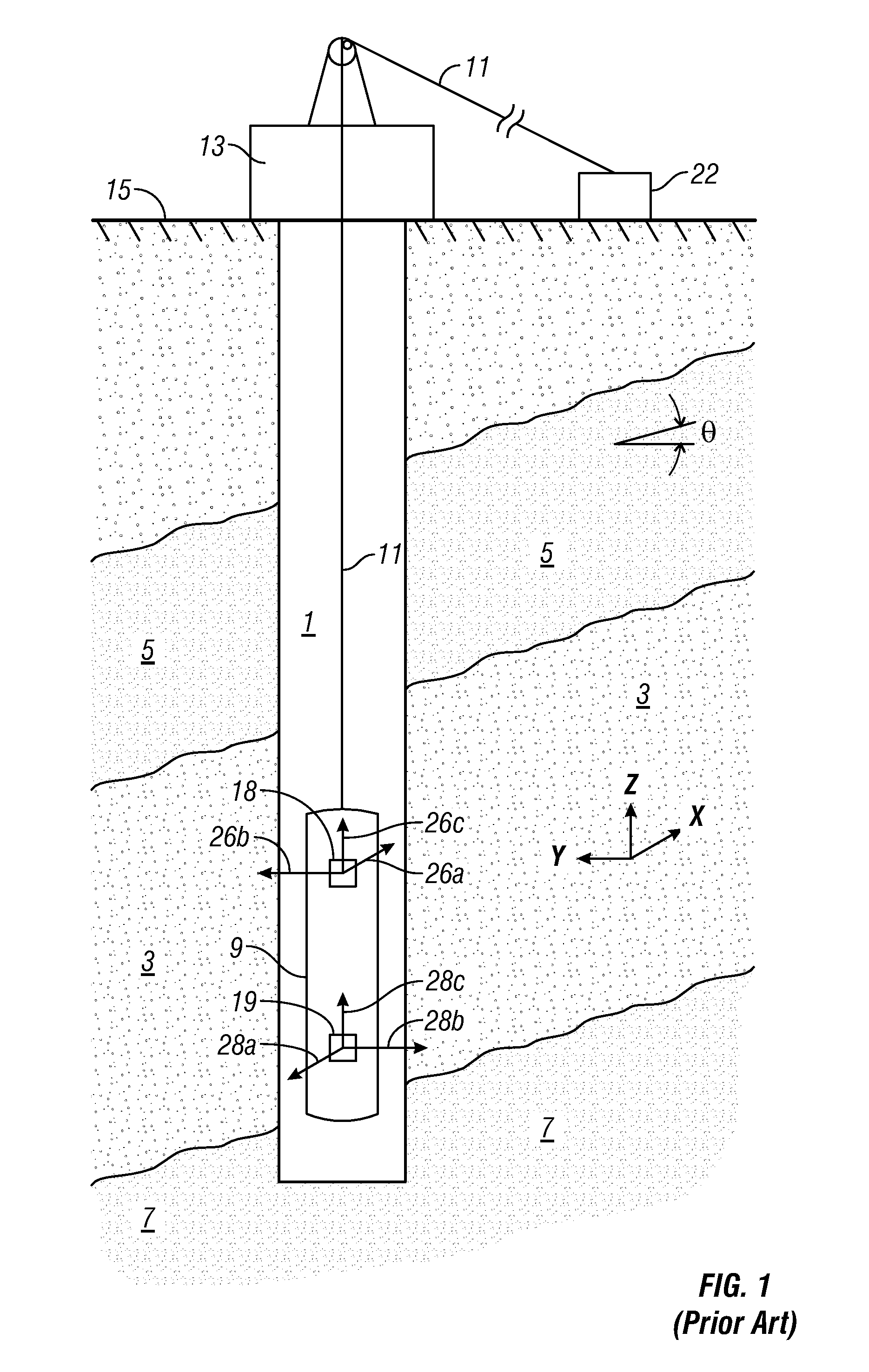
[0038]The disclosure will now be described in more detail and by way of example with reference to the accompanying drawings. FIG. 1 schematically shows a wellbore 1 extending into a laminated earth formation, into which wellbore an induction logging tool as used according to the present disclosure has been lowered. The wellbore in FIG. 1 extends into an earth formation which includes a hydrocarbon-bearing sand layer 3 located between an upper shale layer 5 and a higher conductivity than the hydrocarbon bearing sand layer 3. An induction logging tool 9 used in the practice of the disclosure has bee...


PUM


Abstract

A reactance is introduced into a flow path of axial currents in an induction logging tool. The reactance may be a capacitor or an inductor. A transmitter antenna is operated at a frequency defined by a cutoff frequency related to the reactance.

Description

CROSS REFERENCE TO RELATED APPLICATIONS[0001]The present application is a continuation-in-part of and claims priority from U.S. patent application Ser. No. 11 / 627,172 which is a continuation-in-part of and claimed priority from U.S. patent application Ser. No. 11 / 371, 052 filed on the Mar. 8, 2006, claiming priority from U.S. patent application Ser. No. 10 / 841,397 filed on May 7, 2004, and U.S. patent application Ser. No. 11 / 340,785 filed on Jan. 26, 2006.BACKGROUND OF THE DISCLOSURE[0002]1. Field of the Disclosure[0003]The present disclosure is related to the field of apparatus design in the field of oil exploration. In particular, the present disclosure describes a method for calibrating multicomponent logging devices used for detecting the presence of oil in boreholes penetrating a geological formation.[0004]2. Description of the Related Art[0005]Electromagnetic induction resistivity well logging instruments are well known in the art. Electromagnetic induction resistivity well lo...

Claims


Application Information

Patent Timeline
IPC IPC(8): G01V3/28
CPCG01V3/28
Inventor FORGANG, STANISLAV W.GOLD, RANDYPELEGRI, LUIS M.
Owner BAKER HUGHES INC
Why Eureka
Try Eureka